
14. Common chores#
In this section, a variety of procedures around the beamline are explained in detail.
14.1. Search the Hutch#
The buttons on the hutch interlock panel are labeled with black stickers with white numbers. Those labels correspond to the numbering in these lists. Note that there is no step #4 when opening the hutch and no step #2 when closing.
14.1.1. To OPEN the hutch#
Close the shutter
Press the “SBE” button
∙∙∙
Make sure the “Front Left Maglock” button is not green
Press the green “Open Door” button, wait for the slow door to open
Enter the hutch
14.1.2. To CLOSE the hutch#
Everyone but the person performing the search should leave the hutch.
The search is done by and only one person. Only one person pushes all the buttons. The serach is not a team sport!
Complete the hutch search
Wait for others to exit the hutch
Look in the mirror to see that no one is behind the table
Press search button 1
Visually inspect the length of the hutch, verifying that it is empty of people
Press search button 2
Exit the hutch
∙∙∙
Push the “Front Left Maglock” button. It should be lit green
Push and hold the yellow “Close Door” button. Listen for the magnetic latch
Push the “SBE” button, wait for the loud noise to finish
You can now open the shutter
14.1.3. Hutch search sign#
These instructions are printed, laminated, mounted on a magnetic sheet, and hung near the search station. I would like to make these signs in various languages. If you would like to help by translating this sign, download the Word document below. Make a translation into your language and mail the Word doc back to Bruce. He will print and mount the new translation! I am most eager for Chinese, Russian, and German translations.
14.2. Change energy and prepare for fluorescence measurements#
In this example, we are using Fe as the example. That is, we assume
you are moving the beamline to the state in which it is ready to
measure at the Fe K edge. For any other edge, simply change Fe to
the appropriate element in the following example.
When you change samples, don’t forget to put the detector in a safe
state before swapping out the sample wheel. Move the detector all the
way back – RE(mv(xafs_detx, 205)) – then put the cap back on the
detector. Once you have secured the new sample wheel, remove the cap
before searching the hutch.
Once the hutch is secured and you are back at the computer:
Change edge with the
RE(change_edge(‘Fe’))command. Wait for it to finish and return to the command line. (See Photon Delivery System, Section 7 for details.)Move the detector to middle position, say, 100:
RE(mv(xafs_detx,
100))
The range of positions for that motor is 205 (farthest back) to about 20 (very close to sample). You can check the lower limit withxafs_detx.limits.Measure an XRF spectra:
%xrf. Remember that you want the OCR (total count rate) to be 200,000 or less on each of the seven channels.Adjust the detector position
RE(mv(xafs_detx, <value>)). Remeasure%xrf. Iterate on the detector position until you get a sensible signal on the detector.Record the detector position (
xafs_detx.positionor the number next todet:in the display (Section 1.3.1) at the top of the top screen) for the current sample in the spreadsheet.Move to a new sample position. To change slots on the ex situ sample wheel:
RE(slot(##)), where the number (##) is between 1 and 24. To change between inner and outer rings of samples:RE(xafs_wheel.inner())andRE(xafs_wheel.outer()). For other sample holders, move the appropriate sample stages.To import the spreadsheet into bsui (the data acquisition program):
xlsx()You will be presented with a list of .xlsx file choices, pick the correct one by number and hit Enter. You will then be presented with a list of tabs in the spreadsheet file, pick the correct tab by number and hit Enter. (See Beamline automation, Section 11 for details.)The output of the
xlsx()command will display the command for reviewing the file (the one with??) and the command for running the measurement sequence (the one withRE( ... )). Check to make sure it looks like bsui correctly imported the information from the spreadsheet (you did remember to save the spreadsheet, yes…?), then start the measurements.
14.3. Align the ex situ sample wheel#
The attractive feature of the ex situ sample wheel is that it makes
it easy to move from sample to sample. Once the wheel is properly
aligned in the beam, the commands RE(slot(#)),
RE(xafs_wheel.inner()), and RE(xafs_wheel.outer()) are all
that’s needed to move from sample to sample.
For this to work, the wheel has to be properly aligned in the frist place.
Once the rotation stage is in place and a wheel is mounted on the stage, place a phosphor screen in front of any slot on the outer ring. The alignment procedure assumes that the initial alignment be done of the outer ring.
Rotate the wheel such that the phosphor screen is in the beam path using
RE(slot(#)), where # is between 1 and 24.Make sure that at least one camera is looking at the phosphor screen.
Secure the hutch and open the shutter.
Move the sample stage in X and Y until you can see the spot of the beam on the phosphor screen when looking through one of the cameras. Use
RE(mvr(xafs_x, <amount>))andRE(mvr(xafs_y, <amount>))to move the stage in X and Y.<amount>is a number – some sensible distance in millimeters.Using
RE(mvr(xafs_x, <amount>))andRE(mvr(xafs_y, <amount>)), move the stage such that the beam is approximately in position to go through the middle of a slot on the outer ring.Rotate the stage to an empty slot using
RE(slot(#)).Run the alignment procedure
RE(find_slot()). This will perform linescans in X and Y to find the position such that the beam is passing through the middle of the slot. The resulting plot should look like something like this: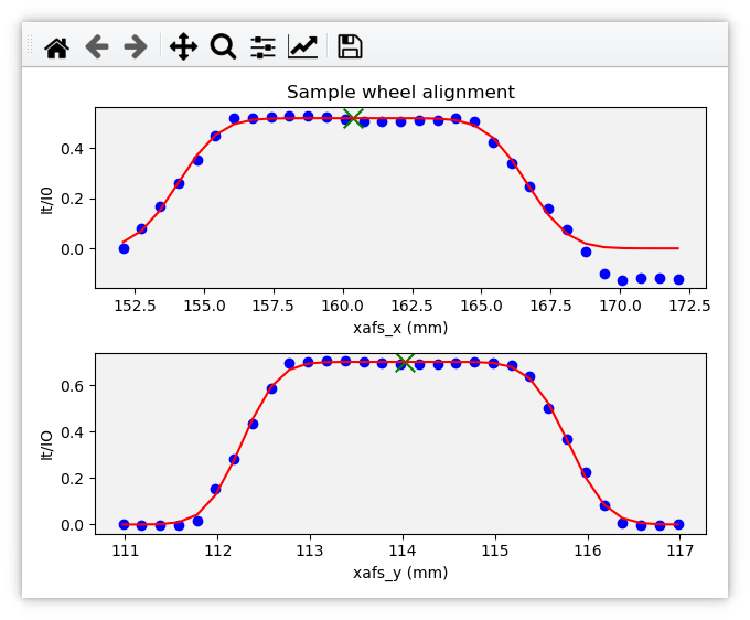
An example of the final plot for an alignment of the ex situ sample wheel. The green X marks shows the aligned positions in
xafs_xandxafs_y.
This procedure sets a parameter specifying the xafs_x position of
the outer ring. The inner ring is known to be 26 mm away. Thus, the
positions of both rings are set. This is why it is important to run
RE(find_slot()) on an outer ring slot.
14.4. Restart the Linkam stage#
When it comes time to change samples in the Linkam stage, it is usually much easier to dismount the stage so that it can be loaded while flat.
14.4.1. Dismount#
Turn off the Linkam controller, the black box sitting on the half rack underneath the XAS table. Reach around behind the unit and press the power button. If using the LN2 siphon, you do not need to power down the siphon box.
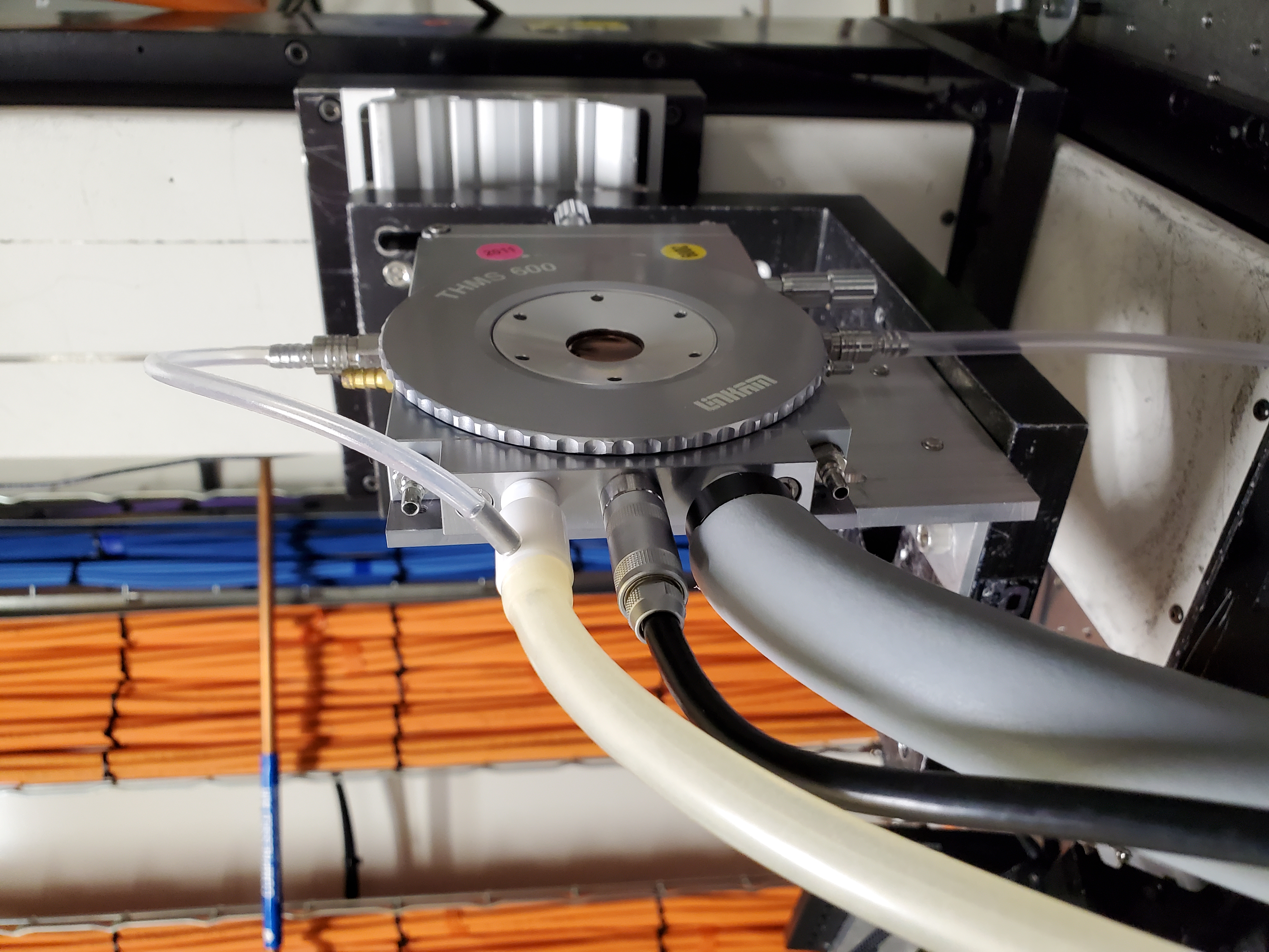
Remove the control cable from the stage. This is the black cable with the barrel connector seen in Figure 5.6. If using the LN2 siphon, also remove the two LN2 hoses, the thick gray and thinner white hoses in that photo.
Unbolt the metal bracket supporting the Linkam stage from the sample stage.
14.4.2. Remount#
Affix the metal bracket to the same position on the sample stage.
Reattach the control cable and the LN2 hoses (if using the LN2 siphon).
If using the LN2 siphon, you may need to blow dry nitrogen gas through the various parts of the system to avoid obstruction of LN2 flow by water ice. 30 seconds of flowing dry nitrogen should be enough to clean out all the lines.
Power up the main Llinkam controller by pressing the power button on the backside of the black box.
At any computer with CSS, reboot the Linkam control software, by following these steps:
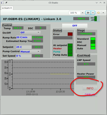
Click the “Info” button on the Linkam screen:
Click the “Reboot” button in the middle of the “IOC Diagnostics” screen
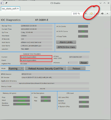
Click the “Reboot now!” button on the “IOC Reboot Confirmation” page.
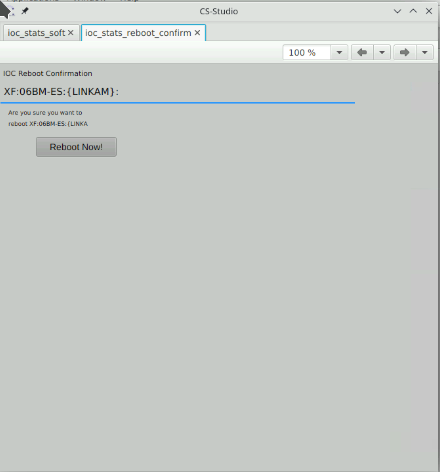
The “Reboot Now!” button will be surrounded by a dashed pink outline while rebooting. When the dashed pink outline goes away, the reboot is finished.
You can close the reboot screen by clicking the little x on its tab. You can then return to the main Linkam screen by clicking the yellow arrow at the top of the “IOC Diagnostics” screen.
You are now ready to begin using the Linkam stage.
14.5. Filling the 25 liter LN2 dewar#
Open both hutch doors. To open the right (manual) door, press the Front Right Maglock button (the green light should go out) on the HMI panel. Push the door open manually.
Open main LN2 valve. Use the button on the “06BM utilities” CSS screen or at the bsui command line do
ln2.open().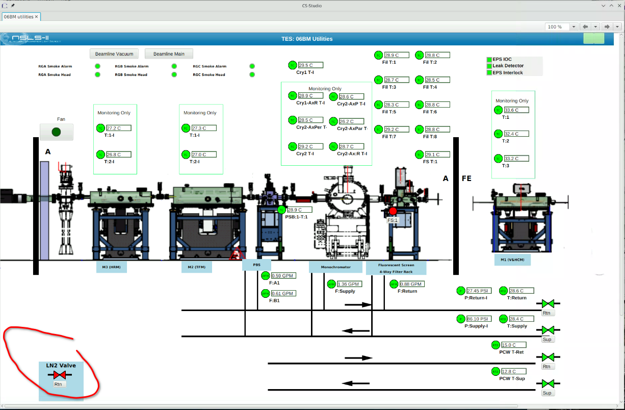
Lower the dewar to the lowest possible position on the blue lift cart.
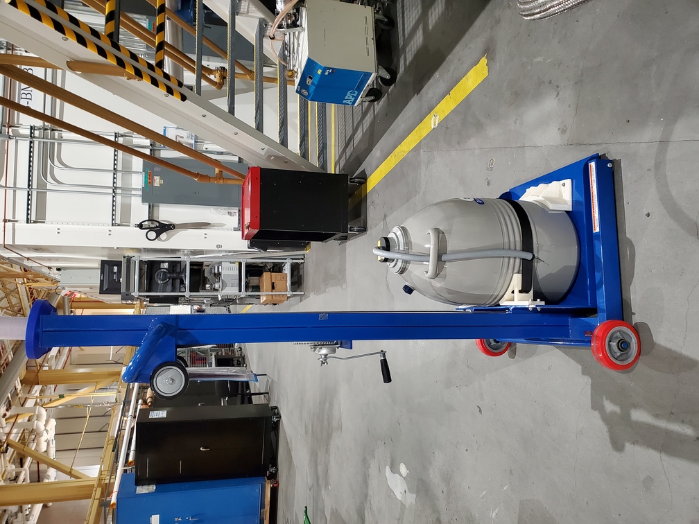
Place the dewar close to the LN2 tap, but some distance away from the O2 sensor on the ODH monitor. If using the 25 L dewar, move it on the cart at all times. (If using the 2 L dewar, secure the top while moving the dewar.)
Don safety glasses, face shield, lab coat, and insulated gloves. All of those things can be found in the hutch.
With gloved hand, place feed line securely in the dewar with the outlet at the bottom of the dewar.
With gloved hand, open the manual valve. Listen to make sure the flow sounds OK. The noise should quiet down once liquid starts flowing. That should take a minute or less.
Monitor the dewar AT ALL TIMES while filling.
Look for the styrofoam float to know when the LN2 level is approaching the top. DO NOT OVERFILL.
When full, using a gloved hand, close the valve in the hutch to stop LN2 flow.
With a gloved hand, remove the feed line from dewar. Slide it into its resting place against the back wall, behind the cable trays.
Move the blue cart back to its position near the experiment. Lift the dewar to its operating height such that the siphon reaches the Linkam stage.
Do not remove glasses, face shield, lab coat, or gloves from the hutch.
Close main LN2 valve. Use the button on the “06BM utilities” CSS screen or at the bsui command line do
ln2.close().Press the Front Right Maglock button. The green light should be on. Manually close the right hutch door.