
D. Ion chamber signal chains#
In the 2023-3 and 2024-1 cycles, BMM went through a transition in how direct beam signals (I0, It, Ir) are measured.
D.1. The old system#
BMM has been using the same ion chambers that were used at X23A2 at the old NSLS. They are excellent ion chambers – robust, linear, easy to use. At BMM, we used a QuadEM electrometer to read the current signal from each ion chamber. The QuadEm is a four-channel device, so I0, It, and Ir were fed into channels 1, 2, and 3. The fourth channel was occasionally used for an electron yield detector.
Voltage was supplied from the same Ortec high voltage supply used at X23A2. The Ortec device sits outside the hutch. The high voltage was fed via cabling through a roof labyrinth and patch panels.
An IOC for reading the QuadEM lives on xf06bm-ioc2 and
communicates with the QuadEM device via a cat6 cable.
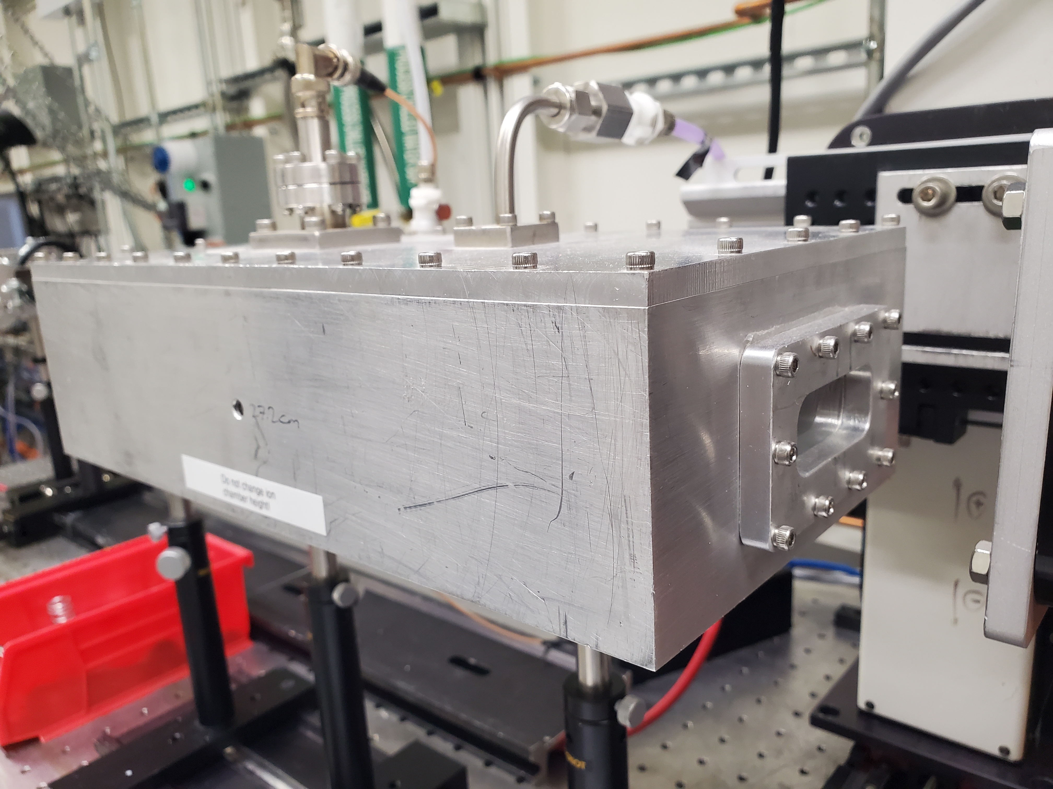
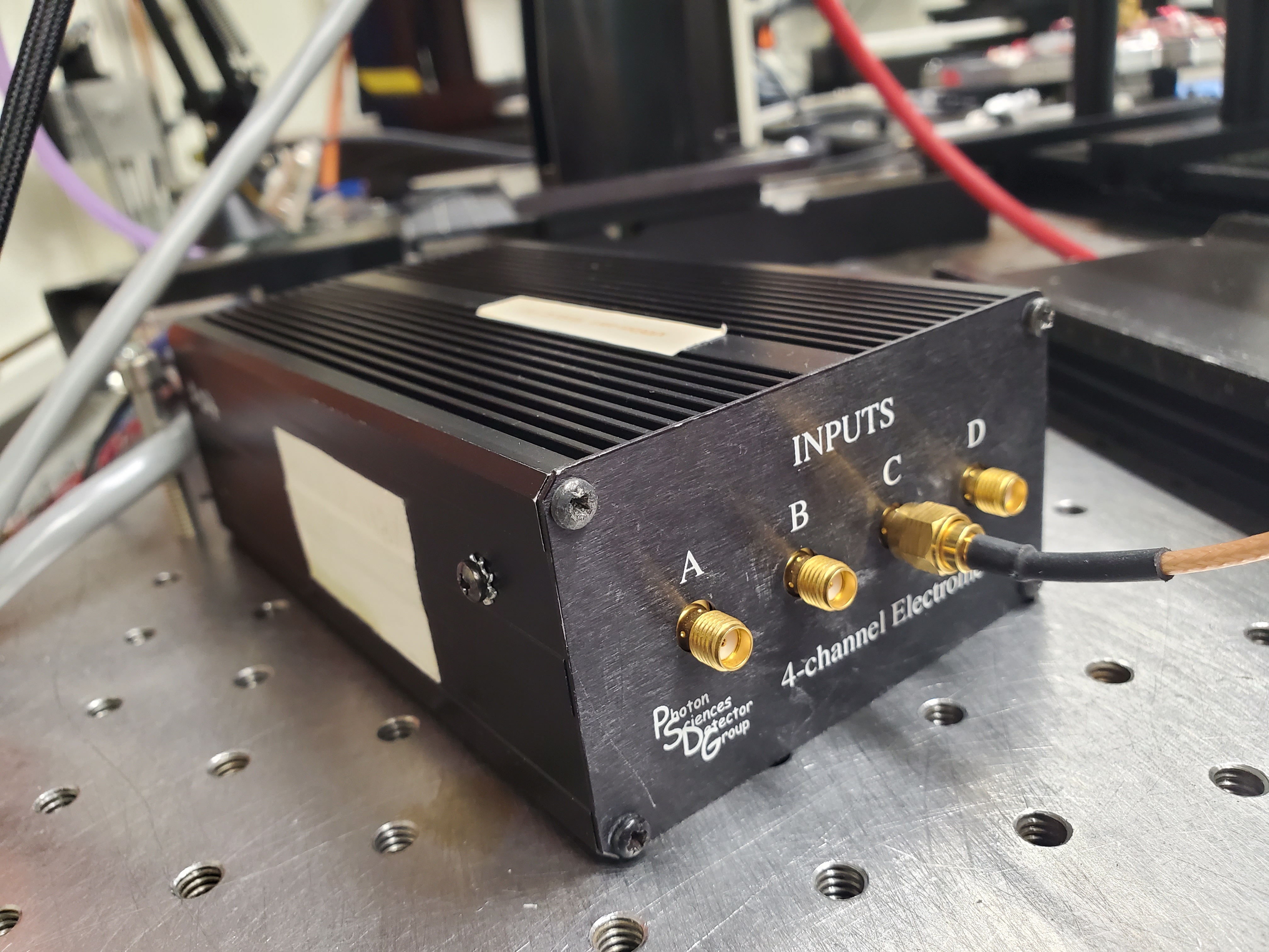
Fig. D.1 (Left) The old Ir detector. (Right) The quadem electrometer used to measure the three old-style ion chambers.#
D.2. The new system#
The new ion chambers are integrated devices. The low half of the enclosure is a gas-filled volume with capacitor plates made from printed circuit board. The plates are guarded at both ends and upright print circuit board pieces are used to guard the fringes of the fields. These upright pieces are strips of copper bridged by surface-mounted resistors acting as a sequence of voltage dividers. This keeps the field lines art the periphery of the capacitor plates nicely parallel.
The upper part of the enclosure has the full signal chain and a voltage supply. This includes an amplifier, an analog-to-digital converter, and a microprocessor running an embedded Debian system and a two-channel version of the QuadEM IOC. The voltage supply is fully adjustable up to 2000 V, but are run at 200 V.
The electronics package and the voltage supply are powered a 6 V DC power supply. A cat6 cable for each ion chamber allows the IOCs to communicate on the INST network.
The ion chambers also have an optical fiber input port so that data can be time stamped with the global timing signal from the accelerator. This will be used in the near future to implement continuous scanning on the monochromator.
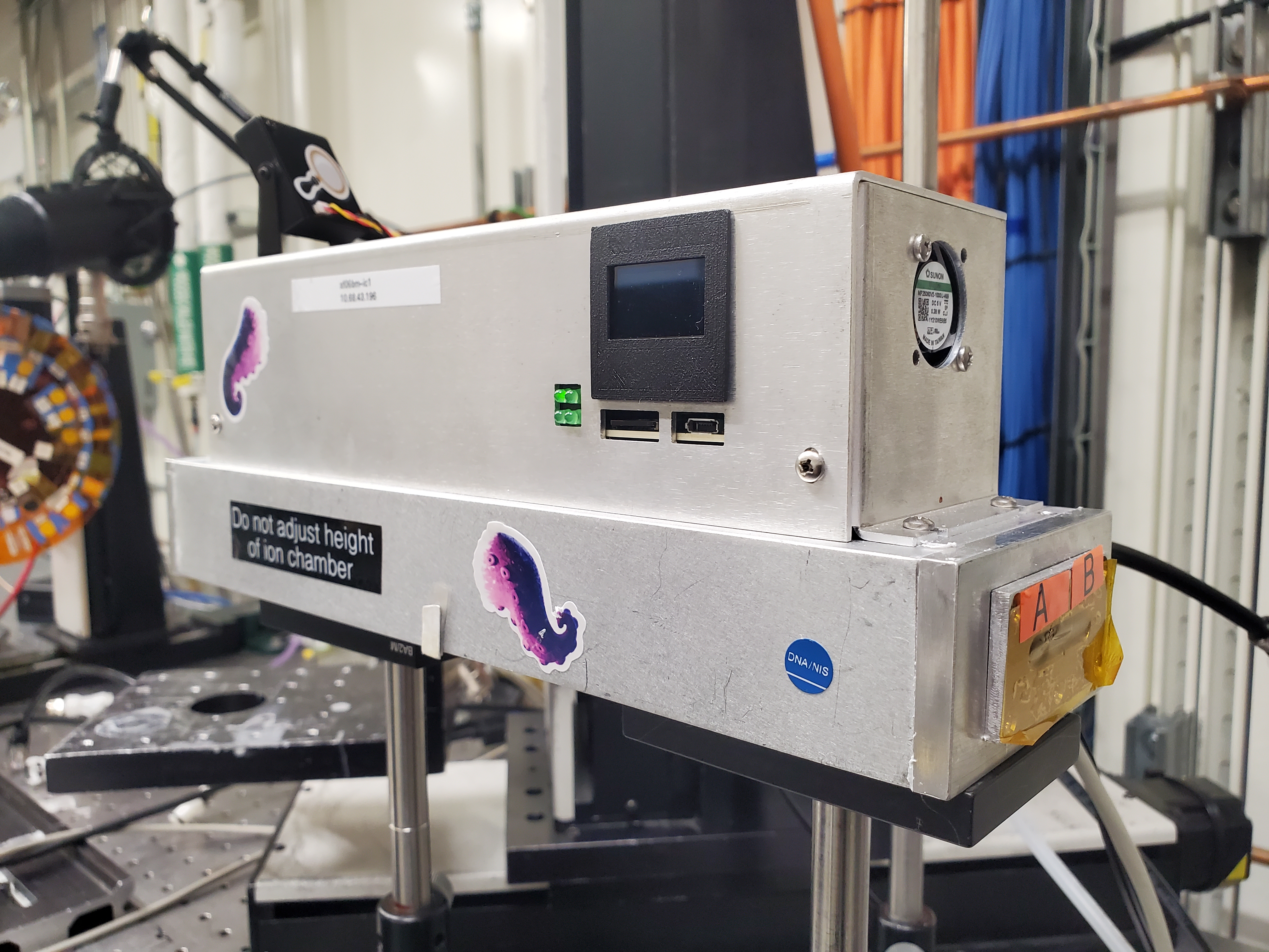
Fig. D.2 The new I0 detector with integrated electronics and voltage supply.#
D.3. Configuration in bsui profile#
It is intended to be easy to configure bsui to switch easily
between ion chambers and electrometers.
In BMM_configuration.ini there are boolean parameters for setting the various electrometer signal chains. These, in turn, set internal parameters in the bsui profile or enabling the different signal chains.
Editing the INI refile will require restarting bsui.
These internal parameters are used to synchronize setting integration times across the various signal chains via the LockedDwellTimes object.
Each new ion chamber in use needs to have its flag set to True.
The QuadEM and each individual ion chamber will be configured if
available on the network. If the network connection cannot be
established, a noisy_det from ophyd.sim is created with the
same name.
Note
Even with all 3 new ion chambers in place and in use, the QuadEM device will still be made. This will allow use of electron yield and other detectors as well as measurement of any other current signals.