
G. Photo Galleries#
G.1. Harmonic Rejection Mirror#
The HRM at BMM is a bounce-down mirror. The light enters as indicated by the yellow arrow. The beam coming from the collimating mirror and mono is inclined upward. In mode D (high energy, non-focusing) (Section 7.3), the HRM makes the beam approximately level with the floor.
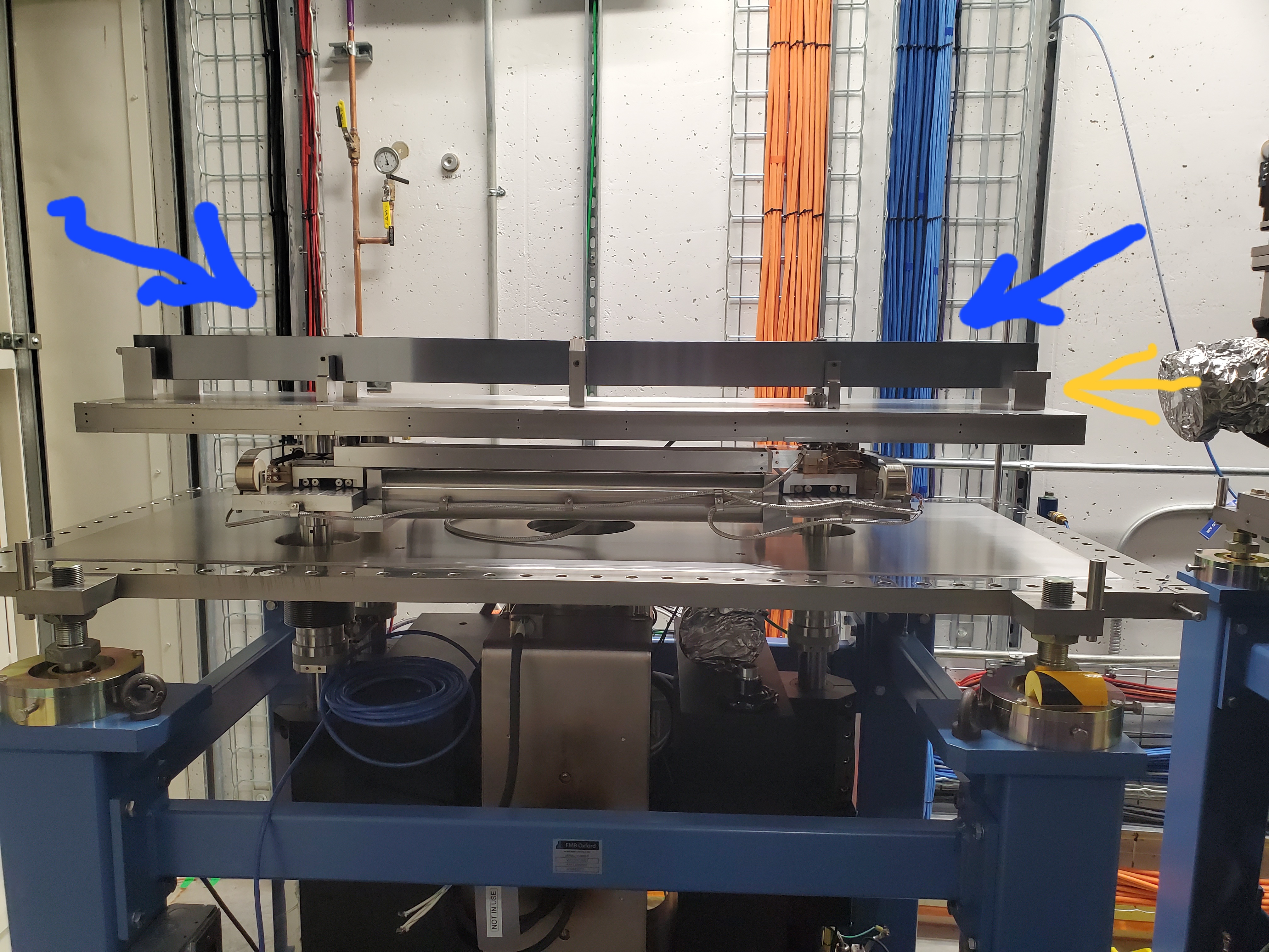
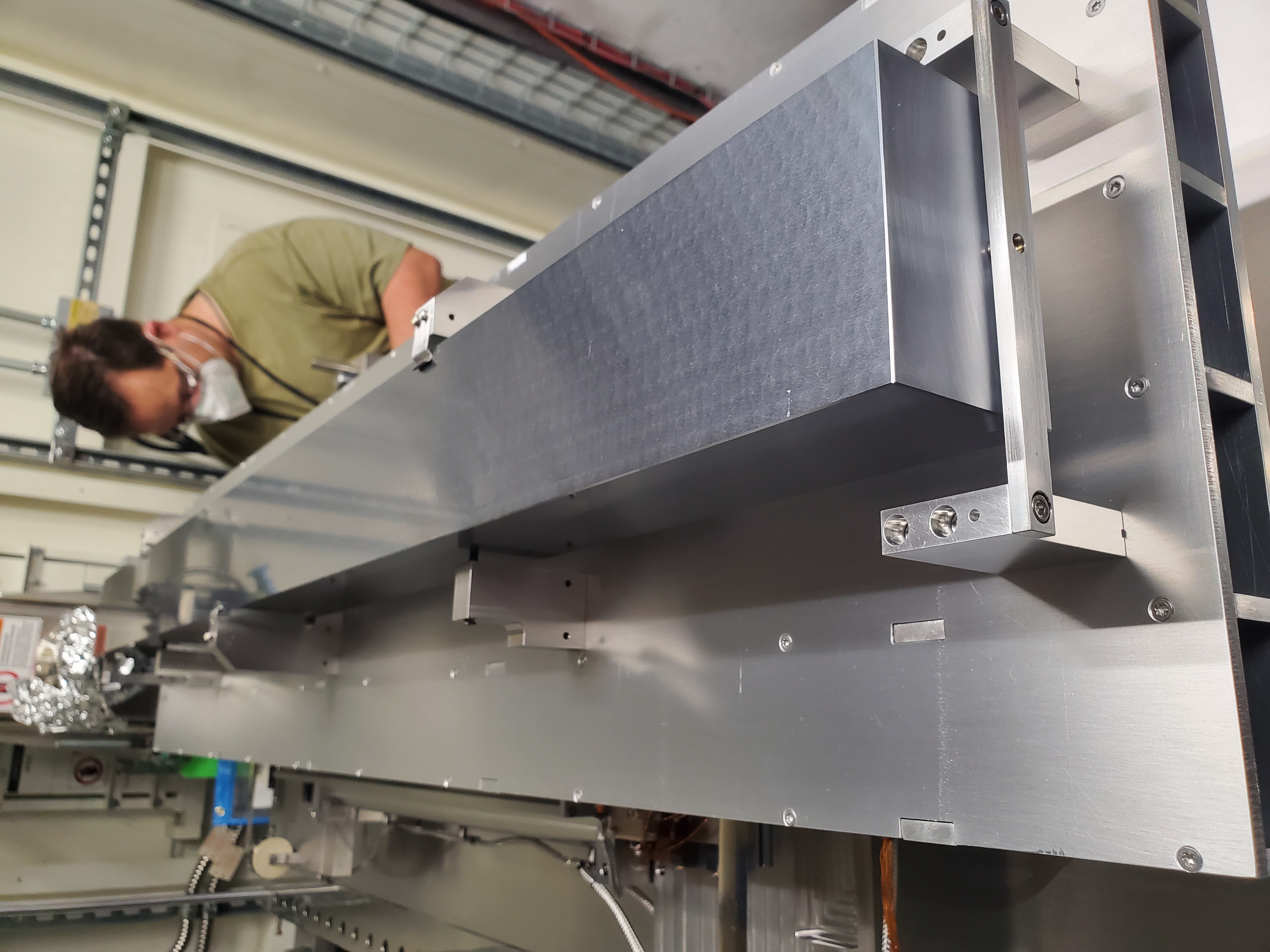
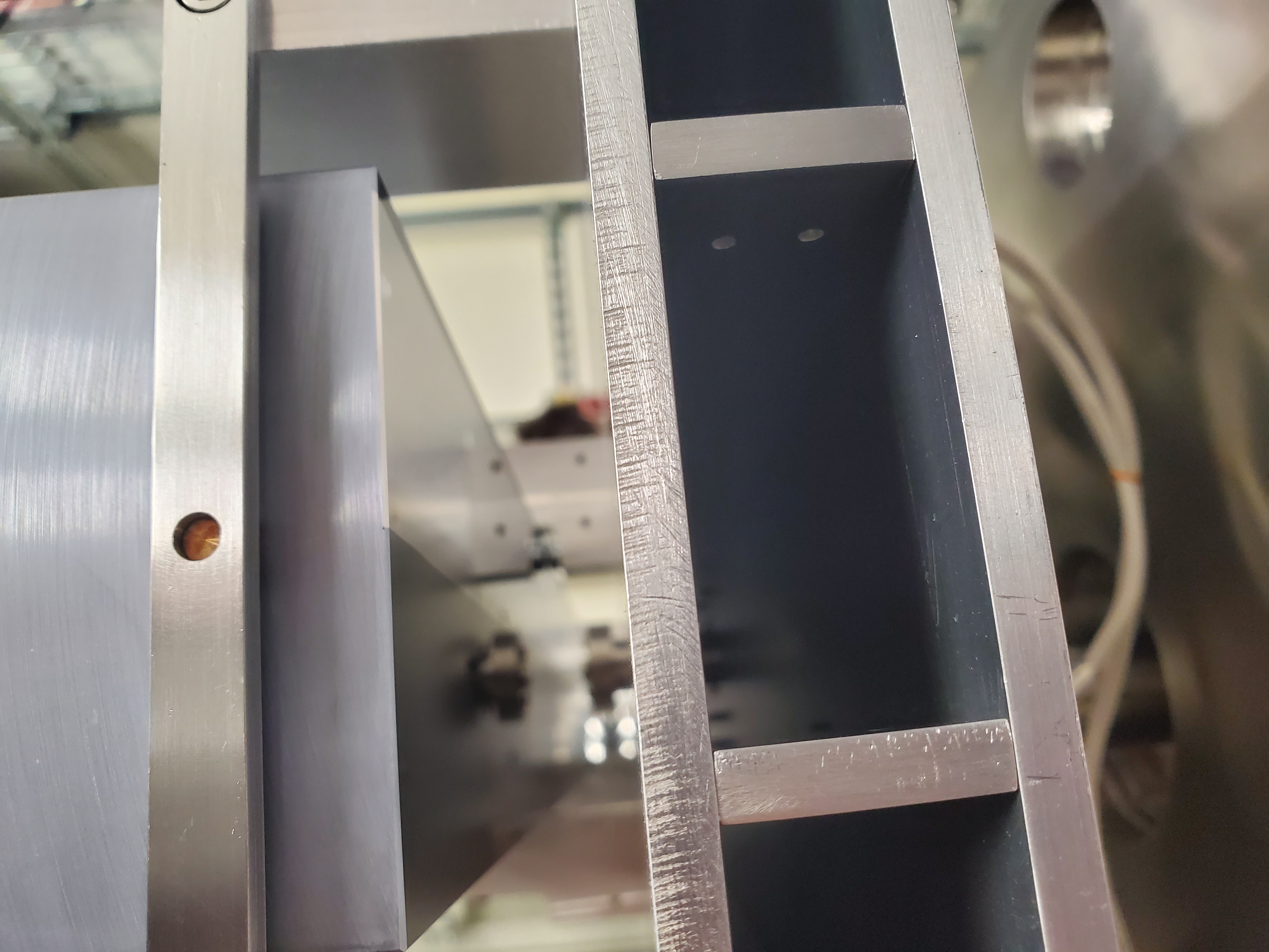
Fig. G.1 (Left) The HRM with the vacuum vessel removed. (Middle) The top of the silicon block of the mirror. This is the non-reflecting side. (Right) The reflecting surface of the mirror. Note the differently colored stripes. The bare silicon is the darker stripe on the left. The Pt/Rh is the brighter stripe on the right.#
G.2. Hoisting#
Here are some notes on heavy things get hoisted at BMM.

Fig. G.2 4 foot strap with buckles through the rings on the cyrostat.#
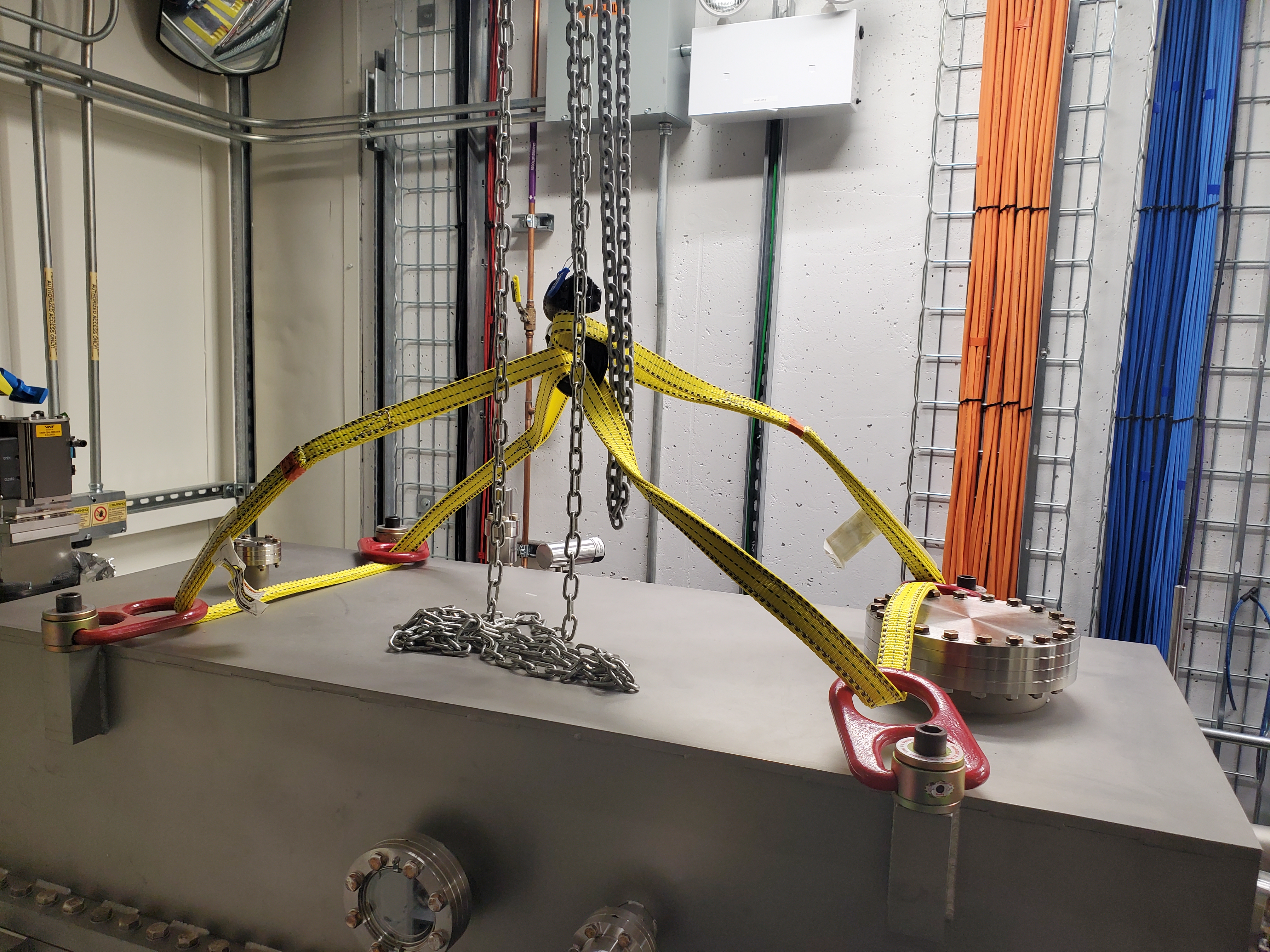
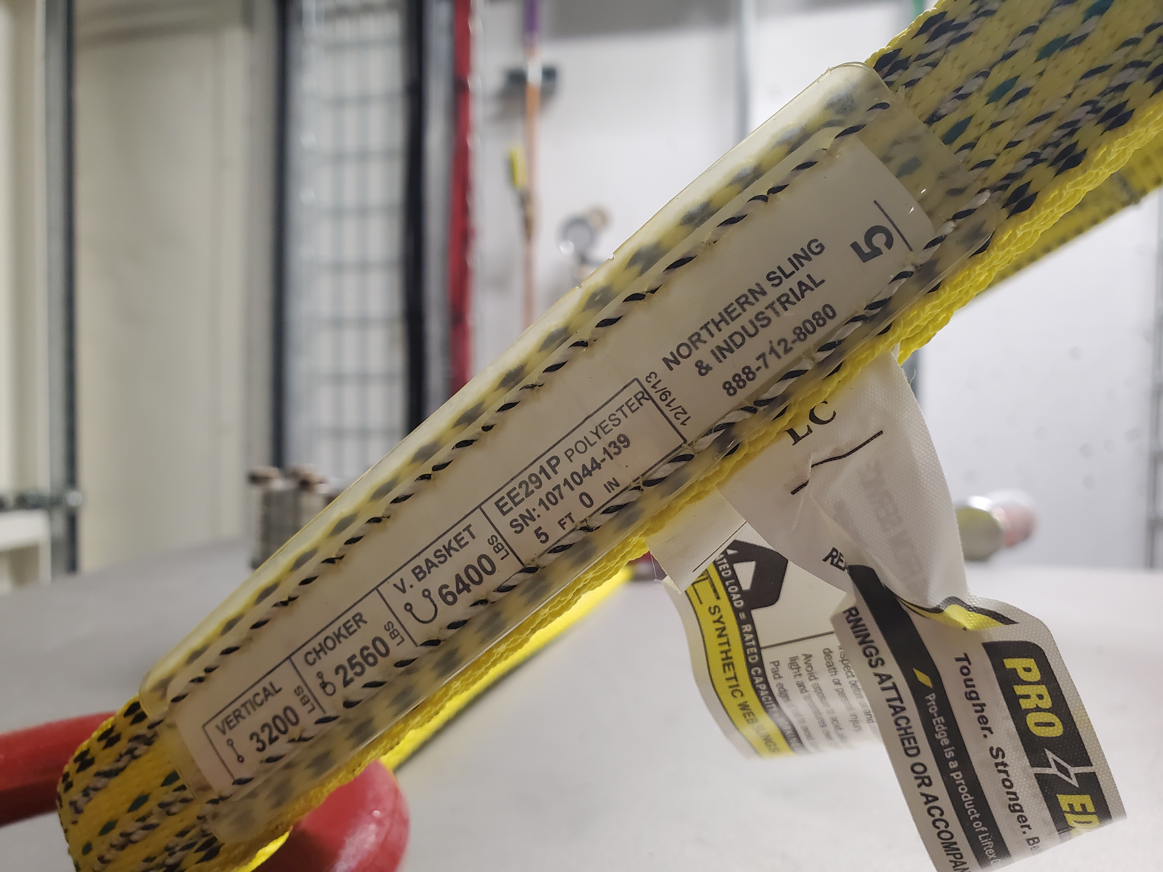
Fig. G.3 Two 5-foot straps + rotating rings at the mount points.#
G.3. DM3 BCT Failure#
May 5, 2023: Failure of the DM3_BCT axis
Symptoms: BCT could not be moved from CSS or bsui. Immediate encoder loss. No motion.
After several times restarting the IOC and one power cycle of the motor controller, I finally thought to take a look at the physical device. This is what I found.
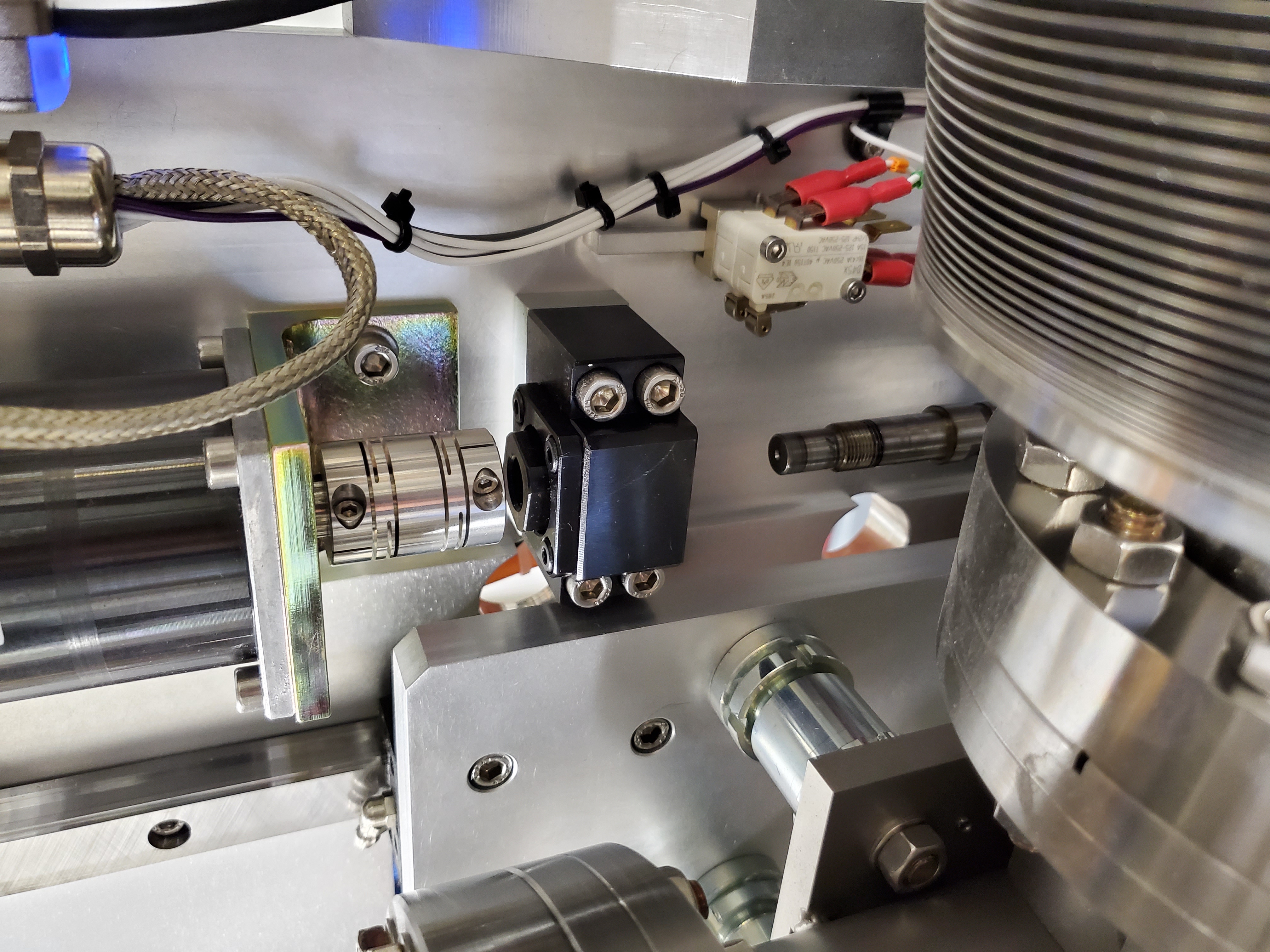
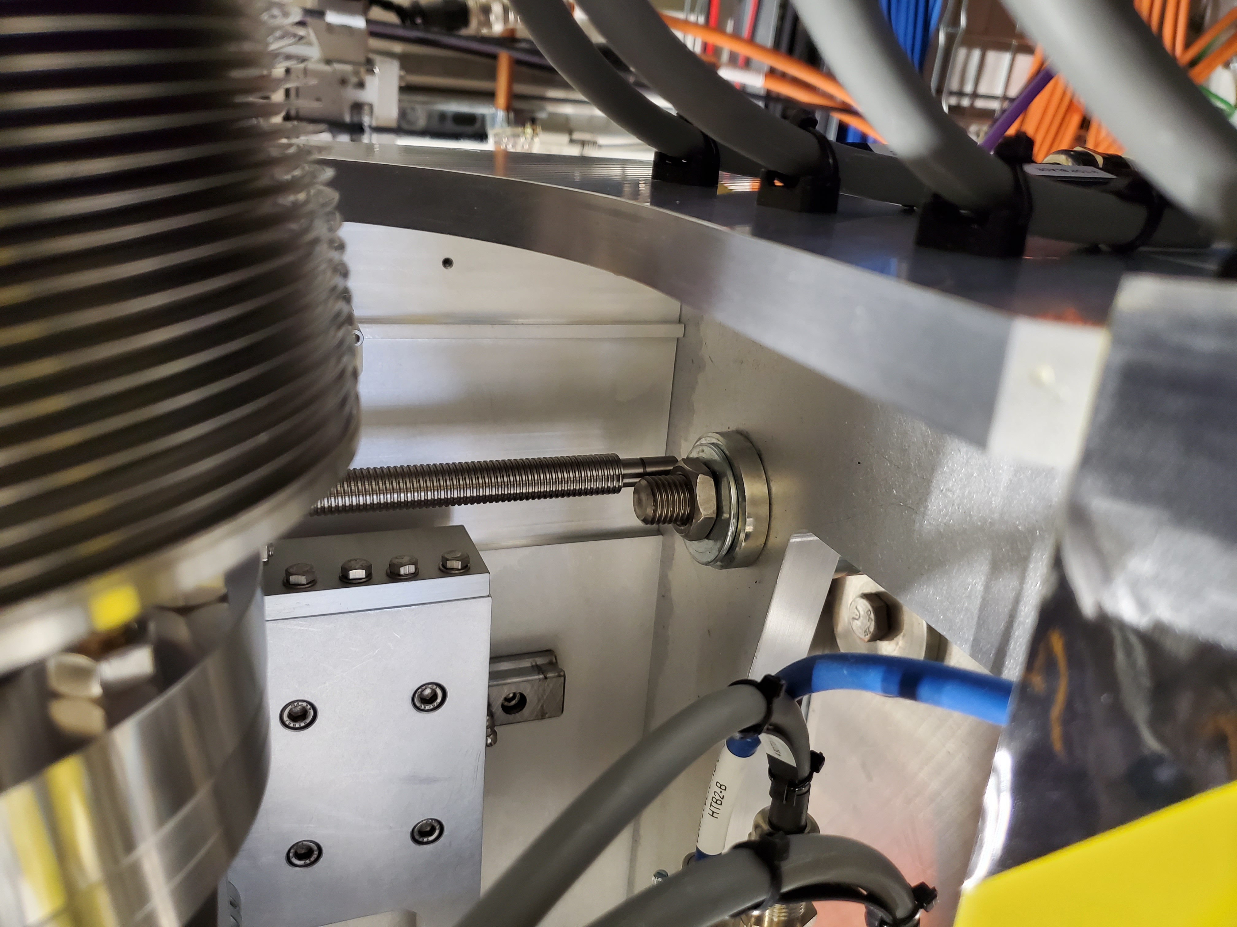
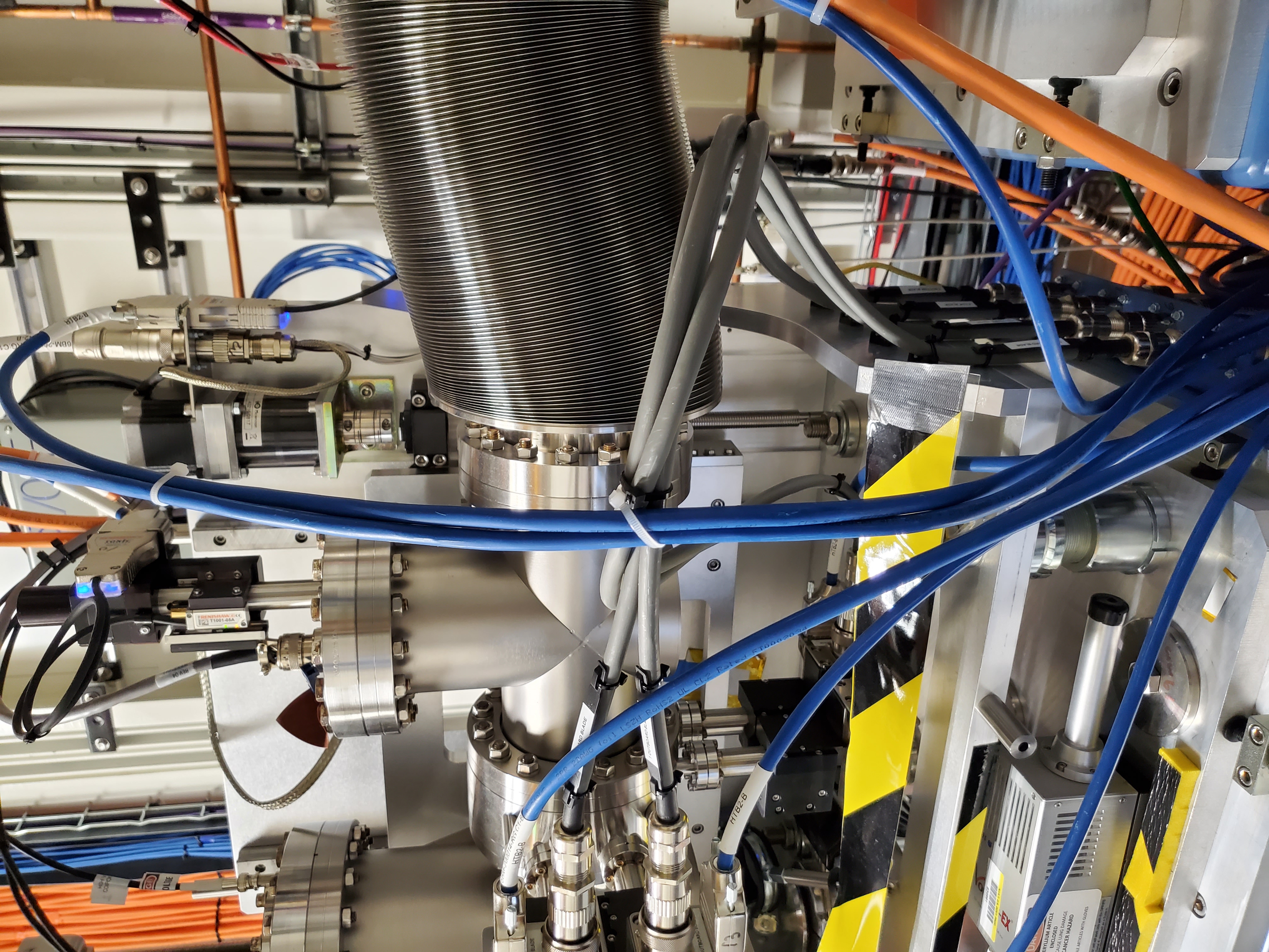
Fig. G.4 The threaded rod had slipped free of the coupler connecting it to the DM3 BCT motor. Once uncoupled, it wound it’s way through the carriages all the way down, finally coming to rest on the base of DM3.#
Solution: Rethread lead screw through upper carriage. Reinsert into coupler. Tighten coupler.
G.4. Three-Pole Wiggler#
Here are some photos of BMM’s three-pole wiggler.
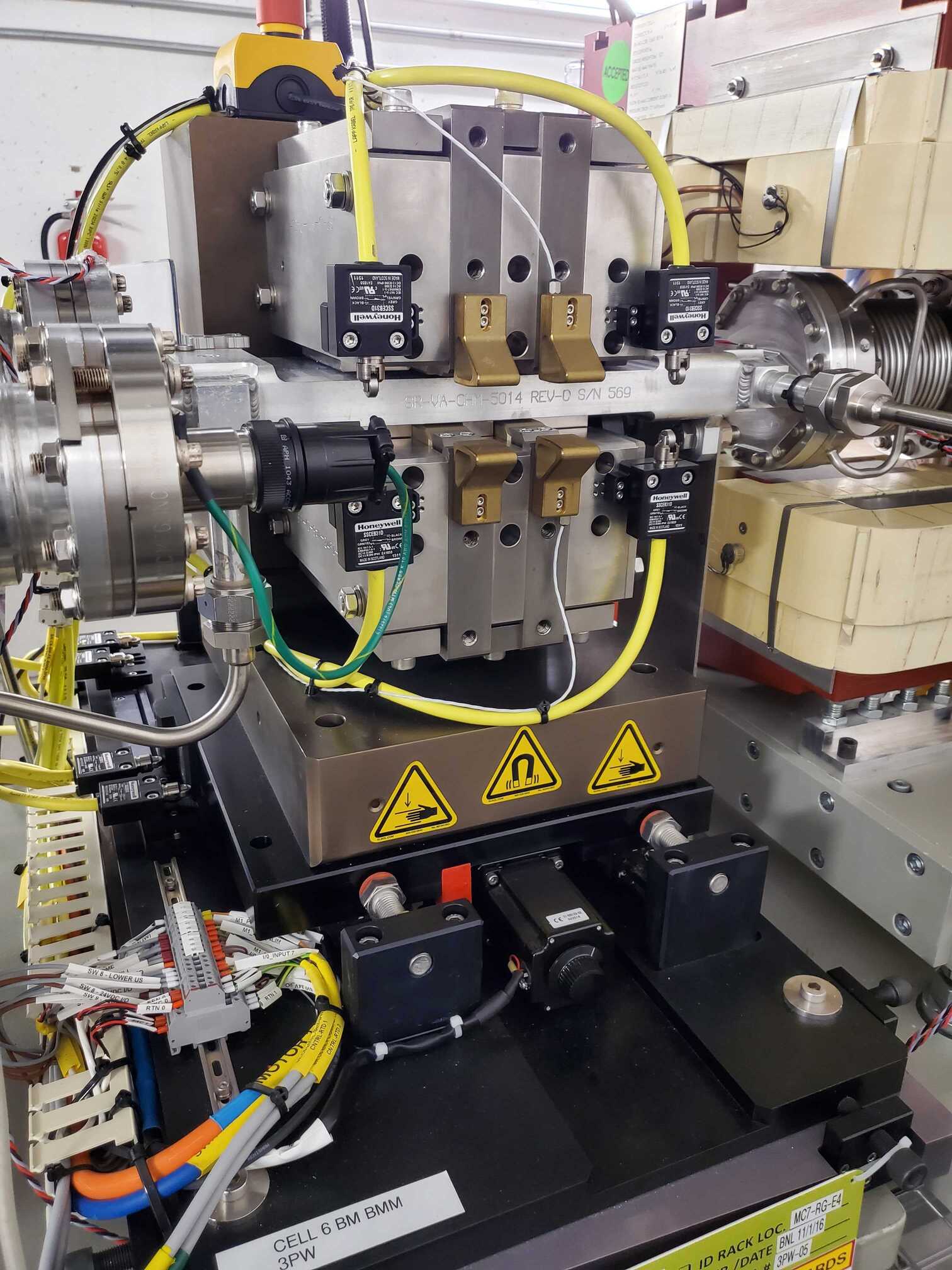
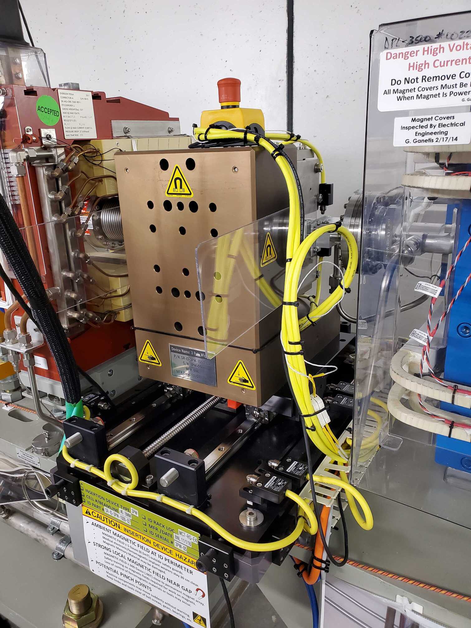
Fig. G.5 (Left) Outboard side of three-pole wiggler. (Right) Inboard side of three-pole wiggler.#
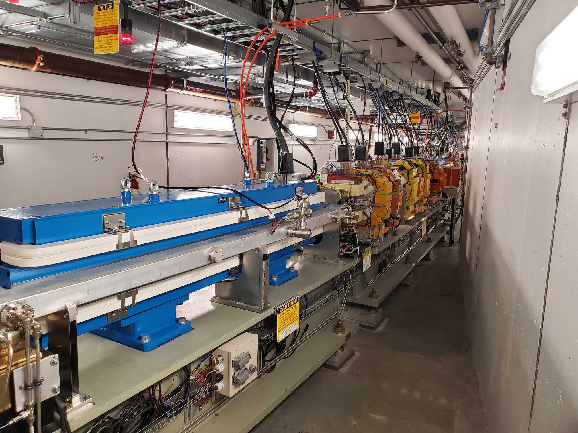
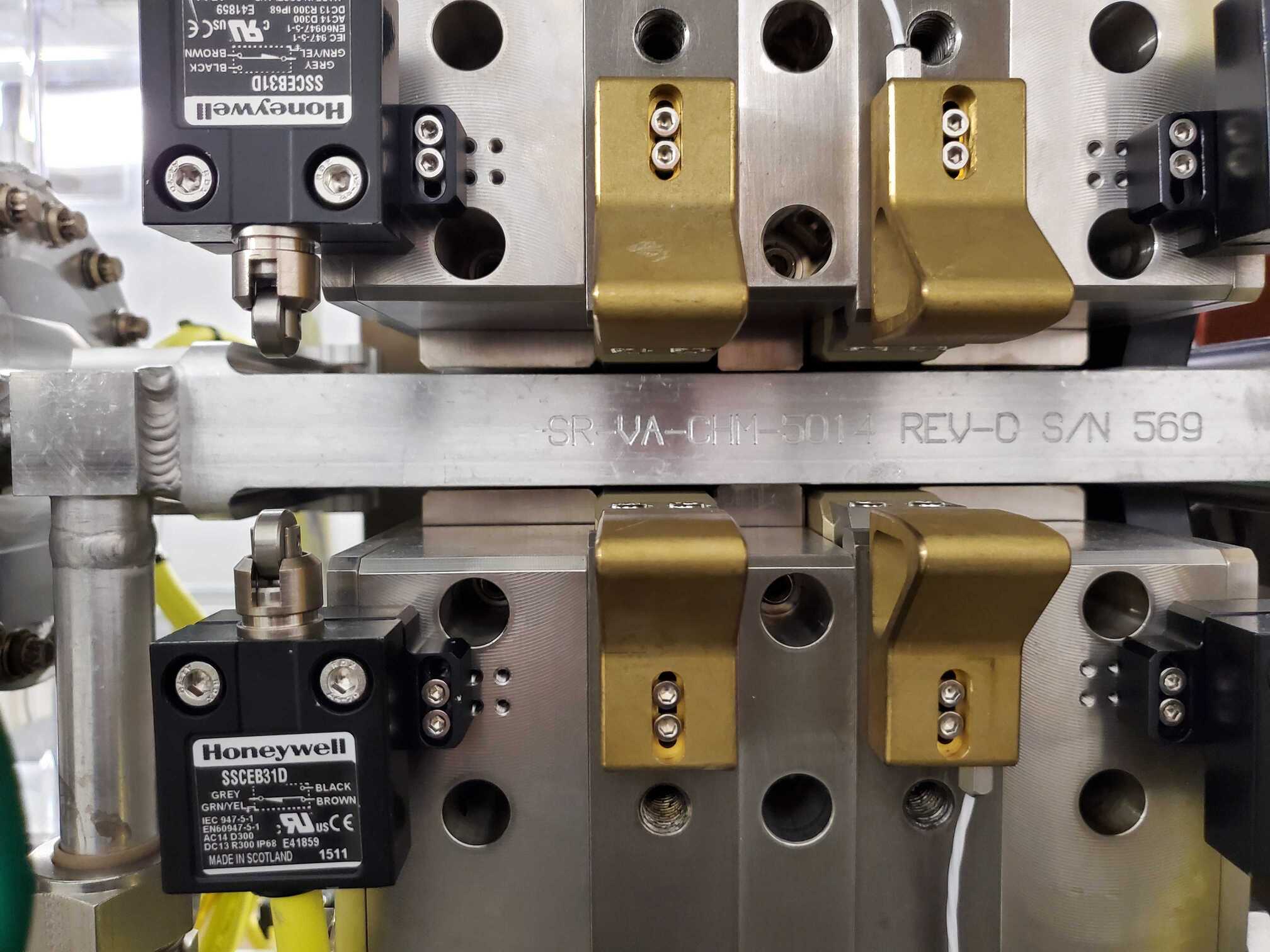
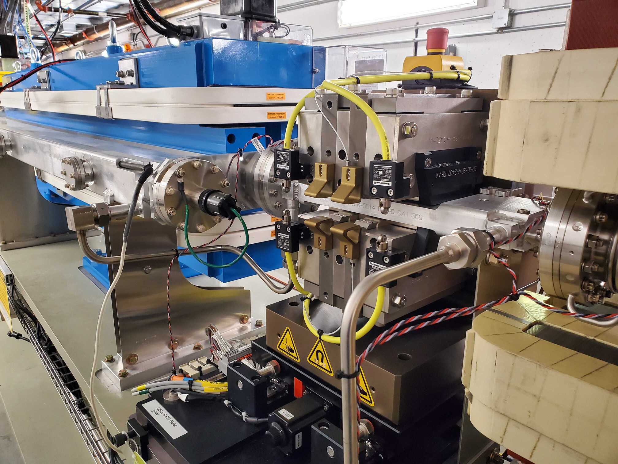
Fig. G.6 (Left) View from downstream. 3PW is just upstream of the bend magnet. (Middle) Close up view of the jaws. (Right) View from upstream.#