
E. Instrumentation Details#
This section is a scattershot assortment of details about things at the beamline, presented in no special order. Subsection titles have been alphebtized to make them a bit easier to find when reading this page. This is basically an attempt to capture institutional knowledge … someplace.
E.1. Analog Video Capture#
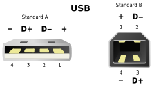
Implementing this USB video adapter to capture video from the small analog cameras in the hutch took a bit of doing.
First, the adapter must be plugged directly into the computer. Using a USB hub makes for an unreliable interface to the camera.
Second, the file /etc/udev/rules.d/99-usb-camera-capture.rules is
needed to set permissions on /dev/video0 correctly when the adapter is
plugged in.
ACTION!="add|change", GOTO="webcam_capture_end"
SUBSYSTEM=="usb", ATTRS{idVendor}=="534d", ATTRS{idProduct}=="0021", MODE="0666"
KERNEL=="video*", ATTRS{idVendor}=="534d", ATTRS{idProduct}=="0021", GROUP="video", MODE="0666"
KERNEL=="video*", ATTRS{idVendor}=="534d", ATTRS{idProduct}=="0021", ATTRS{avoid_reset_quirk}=1
KERNEL=="video*", ATTRS{idVendor}=="534d", ATTRS{idProduct}=="0021", ATTRS{quirks}=0x100
LABEL="webcam_capture_end"
Putting this file in place will require assistance from DSSI. Beamline staff do not have permission to make a file in that folder. See this Jira ticket for an example of what to ask for.
This recognizes the vendor and product IDs of the specific adapter that I bought. When inserted, it sets the device to RW for all users and sets a couple of possibly relevant attributes. (This udev rules file was adapted from the rules file that comes with the easycap dc60 package – info and links here).
Next a small function was written as a wrapper around fswebcam to grab frames from the
camera. The function is basically a wrapper around a call to
fswebcam like so:
fswebcam -d /dev/video0 -r 640x480 -S 30 -F 5 foo.jpg
along with some image processing using python’s wand package.
Required packages:
fswebcampython-wandimagemagick
This whole setup is filled with quirk. There is a delay accessing the
video capture. The -S switch builds in a 1 second delay, giving the
capture device enough time to begin displaying the image. The -F
switch tells the script how many frames to accumulate for good signal.
5 is probably overkill.
In any case, it is now possible to grab screen shots of the currently displayed analog video while collecting data.
All of this is implemented in BMM/camera_device.py for use in
Bluesky. The heart of the implementation is a system call to
fswebcam. From there, the image is saved as an asset and correctly
pointed to in databroker. See:
While this resembles a properly integrated camera and counting on the
anacam object will get recorded in the database, the resource file
– the jpeg image – gets written to the local machine, thus is
not recoverable via Tiled. A future todo would be to make a caproto
IOC as a wrapper around fswebcam and give it proper authority to
write to storage.
Update
As of December 2024, this has been captured in BMM’s ansible configuration. Thus xf06bm-ws3 should always have this udev rule available, even after a system upgrade or installation.
E.2. Beamline maintenance tools#
(Copied verbatim from wiki page. Links and other information should be verified. February 2025)
E.2.1. Motor Controllers#
On the Windows Laptop, use PEWIN. PMAC User’s Manual
The motor controllers are 10.6.130.81, .82, etc. You can communicate using PEWIN with the laptop on the 10.6.130.X network, with the laptop plugged into a DHCP port (it’s address will be 10.6.128.213), or using a USB cable. Unplug the network adapter from the Delta Tau before plugging in the USB cable. The USB cable is the sort with an A-type plug on one end and a B-type on the other end.
E.2.2. MOXA Configuration#
On the Windows Laptop, use the NPort Admin Suite. It is pretty self-explanatory. Put the computer on the 10.6.130.X network, then ask the suite to do a search. When it finds a MOXA device (they should be 10.6.130.51, .52, etc), click on the configure button. It will query the device, then give a fairly self-explanatory set of tabs for configuring things on the device.
NPort5200 User Manual – The small Moxa devices supplied by FMBO are in this series.
Note
The 5200 series is an end of life Moxa product.
E.2.3. Camera Configuration#
On the Windows Laptop, Vimba is the tool for the Allied Vision cameras supplied by FMBO (also the Prosilica GC in use at the XRD end station) for looking at the fluorescence screens in DM1, DM2, and end station FS.
Vimba can also be installed on a Linux machine. From the Quick Start document:
Installing Vimba SDK on Linux Necessary runtime libraries for
executing Vimba Viewer are available with the Vimba download.

+ Vimba ships as a tarball. Uncompress the archive with the command
  ``tar -xf ./AVTVimba.tgz`` to a directory you have writing
  privileges for. This creates a directory named ``AVTVimba``.

+ Navigate to ``AVTVimba/AVTGigETL`` and execute the shell script
  Install.sh with root privileges (for example ``dzdo
  ./Install.sh``).

+ Vimba Viewer is now ready to use, and it can be found in
  ``Vimba/Viewer/Bin``.
The second step is essential or the viewer will be unable to find the cameras on the network.
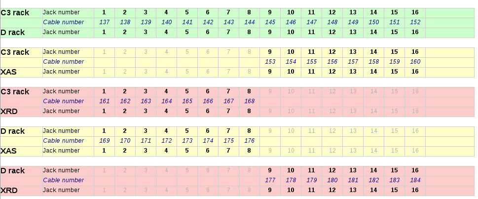
E.3. BNC Cable Map#
Here is an explanation of the BNC and SHV patch panels going between rack D at the control station, Rack C on the roof of the hutch, and the in-hutch patch panel.
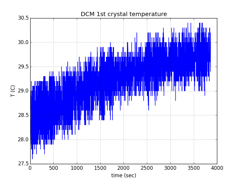
E.4. DCM 1st Xtal Equilibration#
The temperature of the first crystal is measured by a K type thermocouple pressed against the crystal by …. (verify how this is done)
With the front end slits set to 8 mm x 1.5 mm, the DCM first crystal saturates at about 30.5 C from the base cooling water temperature of about 28 C.
This takes about 50 minutes.
E.5. DI Water Flow#
The DI water is controled by manual valves, which should only be operated by the utilities group, and by solenoid valves in the FOE. The solenoid valves are triggered by a water-sensing strip along the floor of the FOE. They are also actuated by switches on the CSS utilities screen. These toggles are the ones circled in pink inthe screenshot on the left.
The valves themselves are the large yellow and black boxes mounted high on the back wall of the FOE. The valve indicators are the rods with orange markings. When the valves are open, the orange marks are facing downstream. When closed, the orange marks are rotated towards the wall. Opening and closing those valves is managed through CSS. They must be open for the utilities group to do their work on the DI delivery to the mono and the filter assemblies.
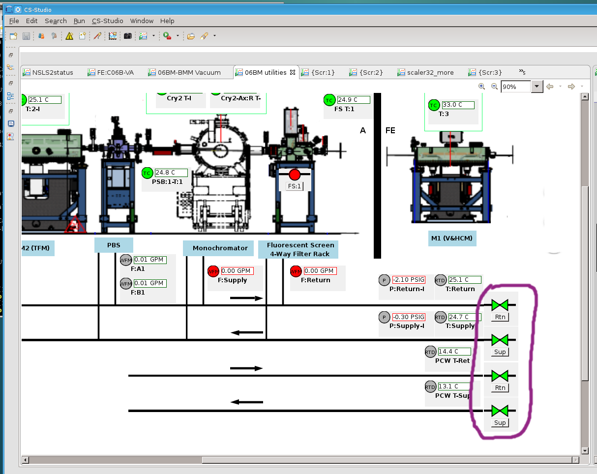
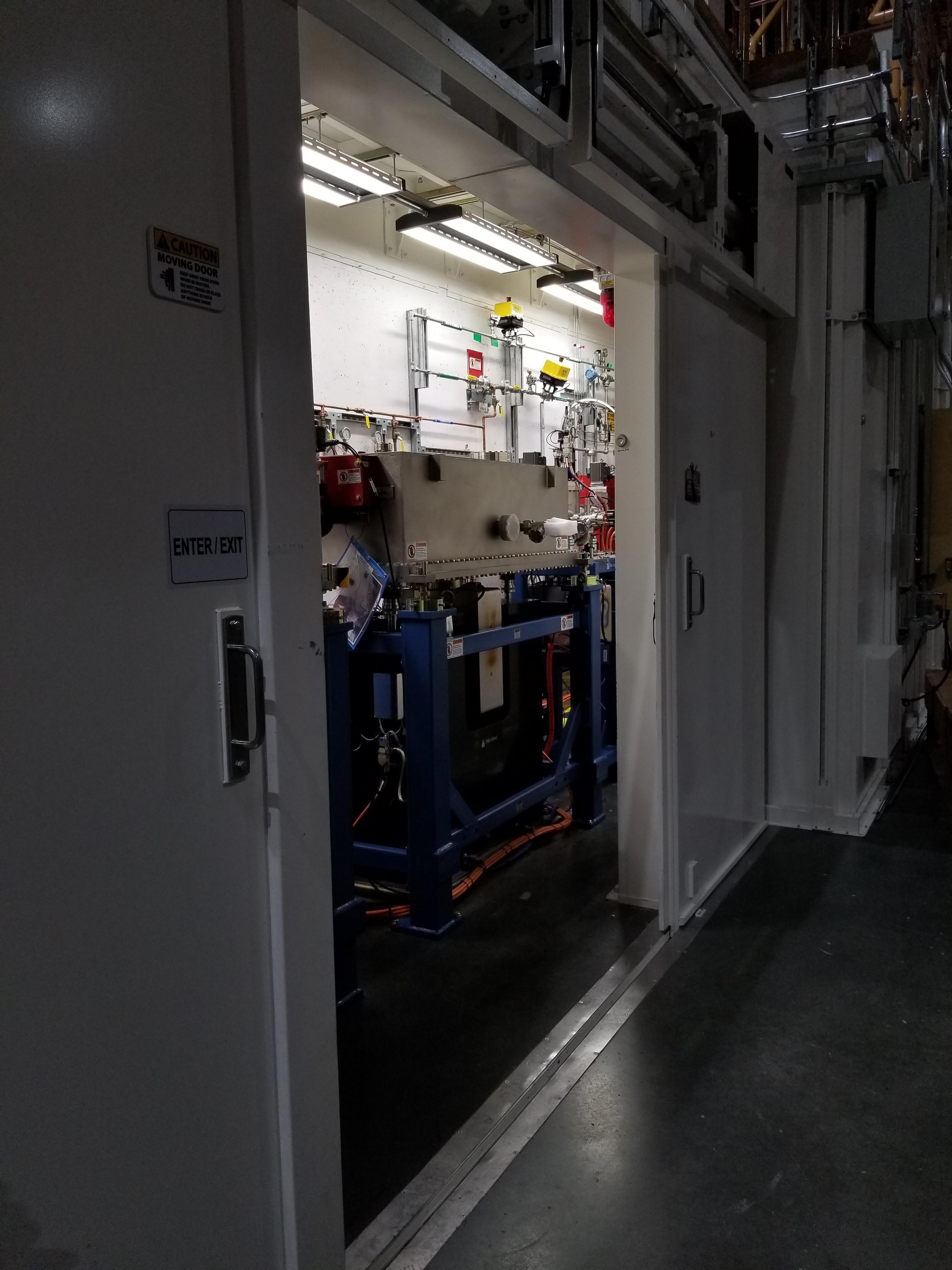
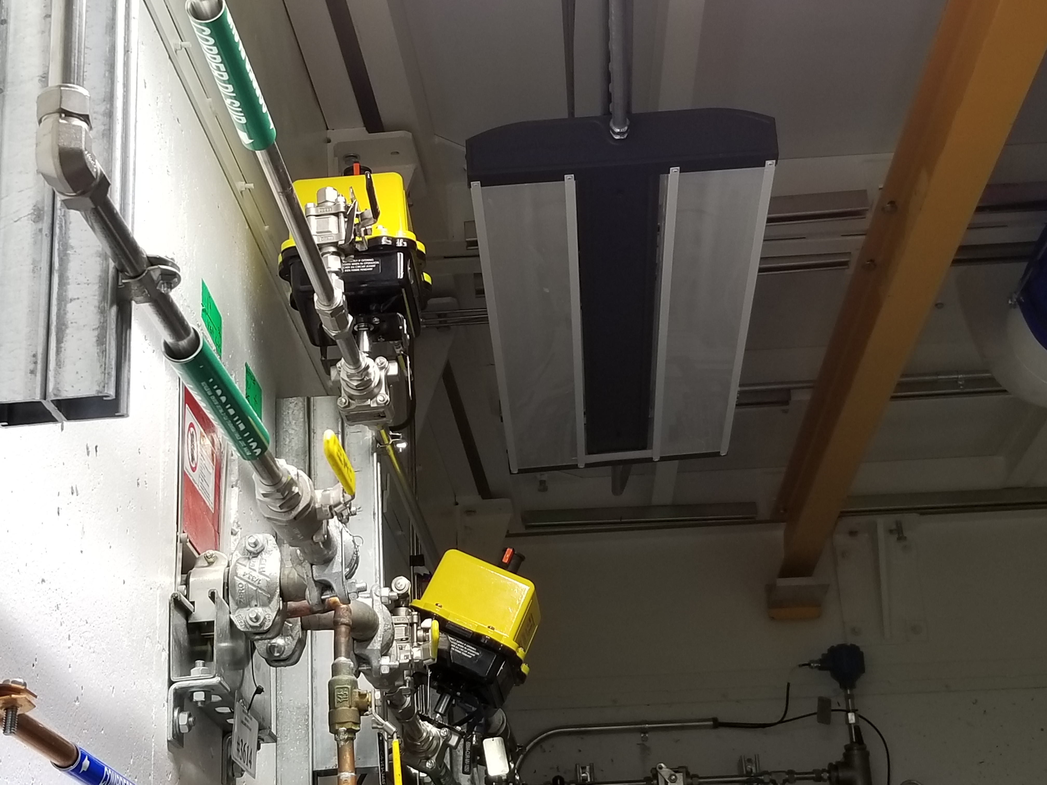
Fig. E.1 (Left) The CSS utilities screen where the water valve controls are found. (Middle) A view into the FOE. (Right) The inboard wall where the physical valve is found.#
E.6. Disabling an MCS8 axis after a move#
E.6.1. From Adam Young at FMBO#
The motors can be disabled after a movement and this can be set at the
Delta Tau level.

First you will need to connect to each MCS8+ with the beamline laptop
and start PEWin.

Then please do the following:

+ Click on the 'View' menu at the top of the window. Then click
  'Program/PLC Status (and upload)'.
+ Select PLC1 and click 'Upload'. An editor showing PLC1 will appear.
+ Scroll down to find the variables P105 to P805. The '1' to '8' part
  of these variables represent axis 1 to 8 on the MCS8+. The value of
  these variables determines whether or not the motors will be
  disabled after a move. They are likely all set to '0' meaning power
  stays on. The lateral motors are on axis 4 and 5 so P405 and P505
  should be set to '1'.
+ Click on the yellow downwards pointing arrow on the toolbar in the
  editor. This downloads the modified PLC1 from the editor to the
  Delta Tau. Close the editor.
+ In the terminal window issue a 'save' to save the modified
  configuration to the Delta Tau non-volatile memory and issue '$$$'
  to refresh the controller.
E.6.2. A follow up from Graeme Elliner, FMBO#
Just done a fast scan of the config file and I think it is probably
because P302=1.

Px02 and Px05 (where x is the motor number) are special Pvars for
setting the final state of the motor once it has stopped moving, they
are used in PLC1x and set as you know in PLC1

If Px02=1 the PLC to check if the motor is in position and its
desired velocity is zero, if these two conditions are set a Flag is
set, If the conditions are still met 1second later then the motor
is put into OPEN LOOP. This means the motor is still enabled but
will ignore the encoder and the motor will hold its current rotary
location. This is useful for the motors that have DPTs pushing
against them in flexures (trapezoidal roll and pitch assy on the
DCMs), it gives a firm base for the DPT to push against but will
not try to hold position (as it would in closed loop) when the DPT
pushes the top part of the stage and moves the encoder.  If Px05=1
then the PLC checks to see if the motor is in position and has zero
velocity, then 1second later it will kill that motor

Due to the way the code is ordered (it looks for thePx02 first) it
will enter Px02 check first, when the conditions are met it will
set the first Flag After that check it then see the Px05 check and
kills the motor. However on the next pass through the PLC it will
again enter the Px02 check, see that the first flag has been set
then trigger the open loop command, re-enabling the motor.

Hence by setting P302=0 in PLC1, it will not go into the check and
not accidentally enable the motor.  If this does not fix it then
the issue is in EPICS
E.6.3. Conclusion#
The above suggestions were done for dm3_bct, a motor that was
showing the re-enable behavior. This made that motor tricky to
operate in bluesky. Setting P302=0 and P305=1 did the trick.
E.7. DM3 CAT6 Patch Panel#
13 more CAT6 ports for use in the hutch. Note that ports listed as SCI/EPICS are tagged ports on both subnets.
This is needed by workstations (like xf06bm-ws5), display machines
running CSS (like xf06bm-disp1), and machines running IOCs (like
xf06bm-xspress3).
Note that xf06bm-em1 needs to be on an INST port while the ion
chambers are on EPICS ports. The difference is that the ion chambers
are running their own on-board IOCs, making them more like IOC servers
than instruments.
Patch |
Port |
xf06bm-a port |
Network |
Role |
Cable number |
DM3-A |
1 |
44 |
EPICS |
xf06bm-ic1 |
200235 |
2 |
45 |
EPICS |
xf06bm-ic2 |
200236 |
|
3 |
46 |
EPICS |
xf06bm-ic3 |
200237 |
|
4 |
06bm-agg 36 |
INST |
xf06bm-em1 |
200238 |
|
DM3-B |
1 |
17 |
SCI/EPICS |
xf06bm-ws5 |
200239 |
2 |
18 |
SCI/EPICS |
xf06bm-disp1 |
200240 |
|
3 |
19 |
SCI/EPICS |
xf06bm-xspress3 |
200241 |
|
4 |
SCI/EPICS |
200242 |
|||
DM3-C |
1 |
200243 |
|||
2 |
200244 |
||||
3 |
200245 |
||||
4 |
200246 |
||||
DM3-D |
1 |
200247 |
|||
2 |
unused |
||||
3 |
unused |
||||
4 |
unused |
Some photos of the patch panel:
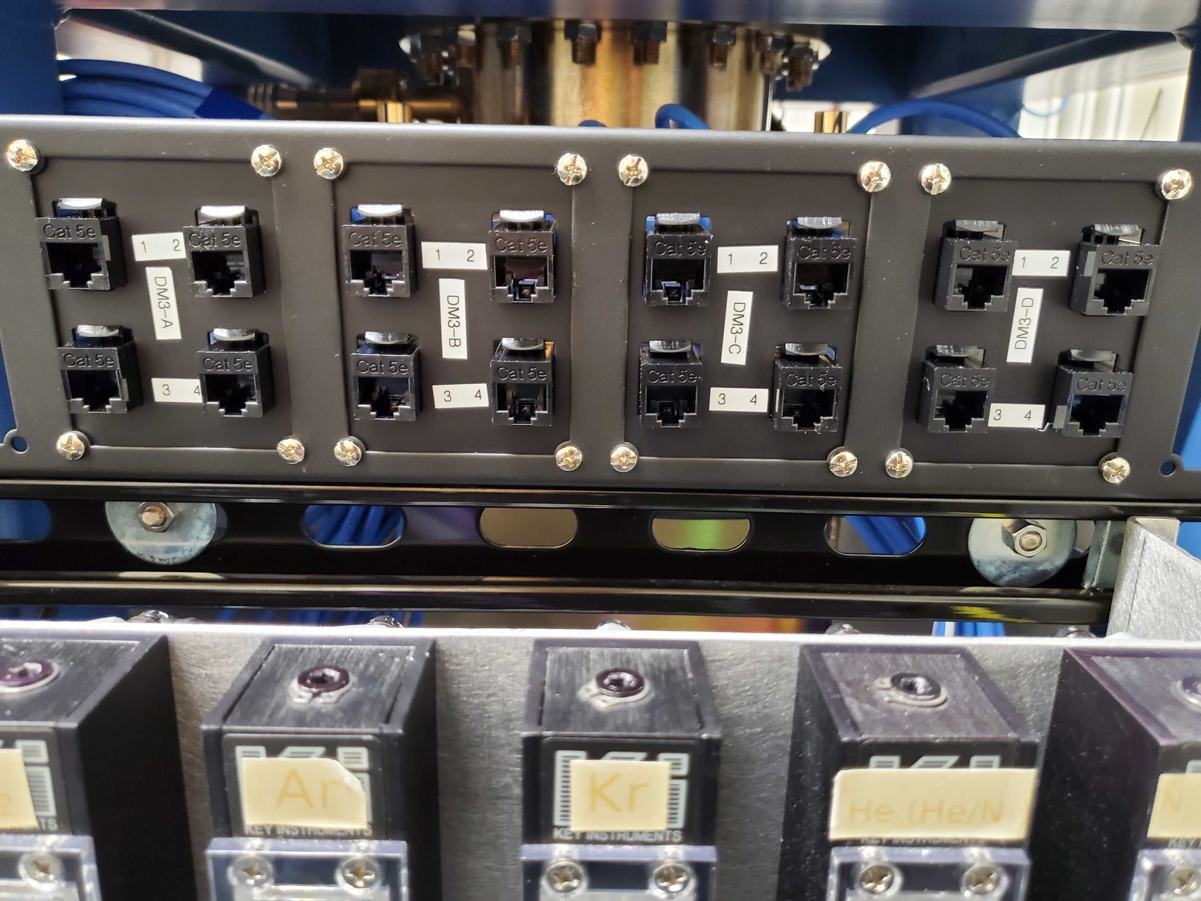
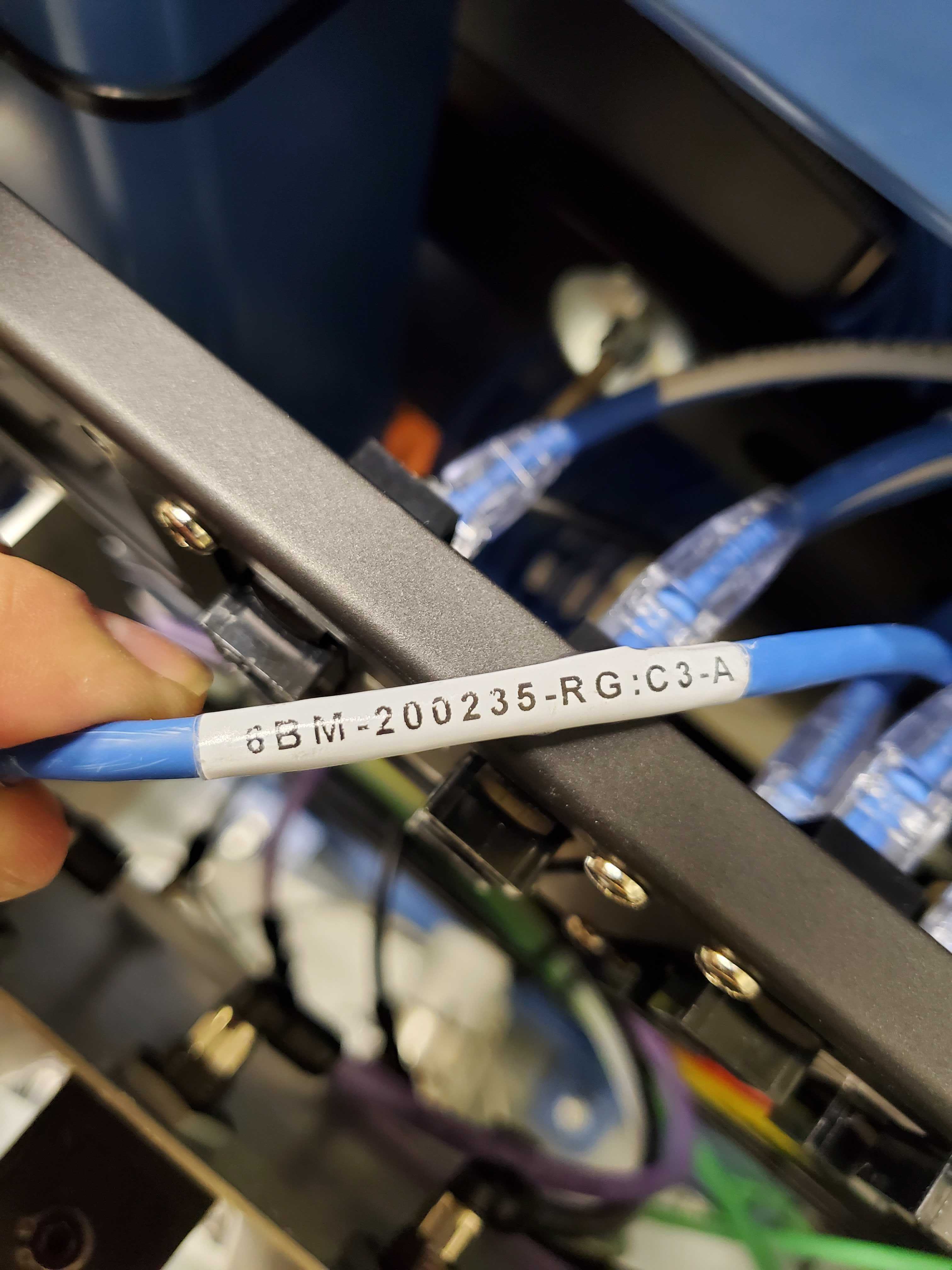
Fig. E.2 (Left) CAT6 patch panel at DM3. (Right) Lowest numbered label on the CAT6 cables in the DM3 patch panel#
E.8. Encoder loss second crystal roll#
On 9 January, 2018, when attempting to home the mono motors following the schduled power outage in December, the 2nd crystal roll motor moved to its negative limit, then reported an encoder loss. With Graeme Elliner’s (an FMB-O controls engineer) help, I came to a resolution of the problem. It has left that axis in an unusual state that needs to be documented.
Executive summary: that axis does not use its encoder. It homes by running to its negative limit, then running back to it’s home position. It does this by counting controller pulses rather than encoder
Here are a couple of useful emails from Graeme to me from January 11 and 12, 2018.
Hi Bruce

We now need to work out where the problem is.
NOTE you will not be able to drive anything while you're doing this or you potentially can break more.
1: Unplug the Disable Plug from the back of the DCM (this will
   force all motors to be disabled) - it’s the small black connector
   (bottom right as you look at the back)
2: Disconnect PL102 & SK102 from IF2
3: Disconnect PL103 & SK103 from IF3
4: Connect PL103 & SK103 to IF2
5: Connect PL102 & SK102 to IF3

IF the Red light on the Interpolator stayed with IF3 then there is
a problem with Interpolator - Need to put motor into Open Loop

IF the Red light on the Interpolator has moved to IF2 then the
Interpolator is fine and it is cabling somewhere - GOTO STEP 6

6: SWAP PL102 and PL103

IF the red light has moved back to IF3 then the problem is between
PL103 to the read head on the Xtal2 Roll stage - GOTO STEP 7

IF the red light has stayed with IF2 then the problem is between SK103 to the MCS8

This cabling is Pin to Pin so a simple continuity test on each pin should identify what has broken

7: SWAP SK102 and SK103. The cabling should now be back to the original layout
8: SWAP SK203-2 and SK203-3 at the feedthroughs on the DCM (FD3-2 & FD3-3 respectively)

IF the red light has moved to IF2 then the problem is INSIDE the
DCM vessel - Need to put motor into Open Loop (and ultimately open
the vessel to find it)

If the red light has stayed on IF3 then there is a problem with the
cable to the DCM. This cable is should be Pin to Pin so a simple
continuity test on each pin should identify what has broken


To Put the Roll Axis into Open Loop
Have you got PeWin working now??
Using Pewin backup the config for the DCM and send it to me please.
A lot of the cable swapping Graeme called for was to try to isolate a bad connection. The connection between read-head and motor controller is rather lengthy, with a vacuum feedthrough, a feedtrough on the side of the service box, and two connections to the interpolators inside the service box.
Following the steps laid out by Graeme, I isolated the problem to being inside the vacuum vessel. Drat! Using the old MC02 configuration I saved to a file, Graeme made some edits as described below and sent me a new configuration file.
Hi Bruce
I have modified the config file to now not use the encoder for
position feedback. I have tested that it downloads with no errors

Details of the mods are listed at the top of the file and below, I
have marked all modifications with either GRE+ (for added code) or
GRE- (for commented code)

In PLC1
P446=0  this disables encoder loss detection for axis4


In the Ivars
I430=700        changed to default stepper gain for no encoder
I432=0          changed to default value for no encoder
I7040=8 this forces the system to use steps for feedback

Use restore config from the backup menu in PEWin to install this
CHECK that the box at the bottom reports NO ERRORS,
in the terminal window you will need to "SAVE" and "$$$".

You will now find that the position scaling will be completely
different now that you are not using the encoder. This means that
your jog speeds will also be different

I strongly suggest NOT trying to use EPICS imediately.

Use the PeWin terminal (or the Jog Ribbon) to move axis 4 to the -ve
limit ("#4j-") at the -ve limit type "#4HMZ" to zero the postion
display and then to the +ve limit ("#4j+").

This will tell you how many steps there are between the limits.

Using this info and the data for the encoded version you should be
able to move th axis to approximately the correct location.

I have noticed that in PLC14 (the homing PLC for axis 4) that even
when the axis was using the encoder the home routine was not using
the encoder home refernce.

It is moving to the -ve limit then moving off 51926 encoder counts,
then setting this to be HOME  -  search for GRE*** in the file.

This will not be correct now the system is using steps and might
actually be more than you have measured as the range in steps.

You will need to change this value before you can use EPICS to home the axis.

Once all this is working in PeWin you can test the homing routine
by entering M1416=1 in the Pewin terminal.
Following this set of instructions, I found that there are 1,218,299 steps between the two limits on the 2nd crystal roll motor. It would seem that there are about 10 or 12 steps per encoder count. The homing procedure works in the sense of finding the negative limit, then moving to a home position. But that home position seems to be about 1/10 of the way between the negative limit and the home-using-encoder-counts.
E.9. Inert Gas Plumbing#
Needle valves are mounted on the outboard side of DM3. Quick connect outlets for the gases are mounted on the upstream/inboard corner of the XAFS table.
Gaseous nitrogen supply
BMM no longer uses a nitrogen cylinder as the supply of N2 for the ion chambers. The house GN2 supplies N2 to the needle valves.
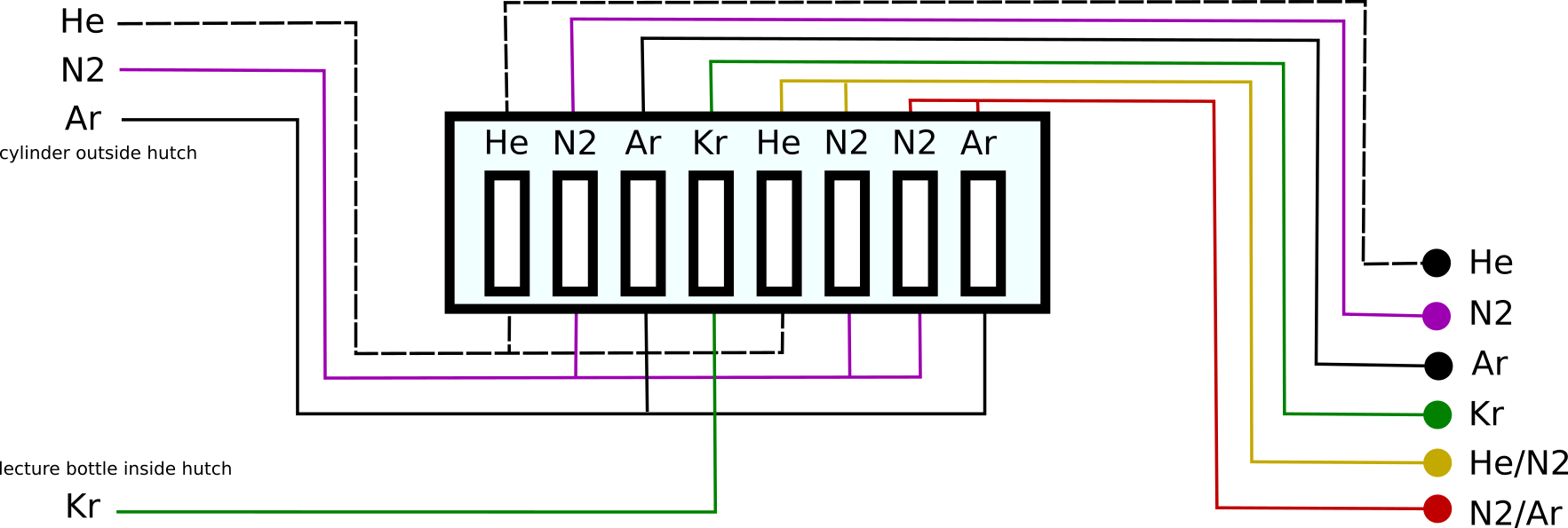
Vendor link for quick-disconnect fixture: https://www.mcmaster.com/5012K122/
In practice, the H2/N2 and N2/Ar mixing channels are not much used. Unless measuring with the incident beam below 5 keV or above 21 keV, it is a poor use of time to make changes to the gas content of the ion chambers. This is because it takes quite some time for the volume of the ion chamber to equillibrate.
N2 is adequate for almost all experiments at BMM. For Tc or Ru, it is helpful to use about 20% Ar. For Sc or lower, 50% He might be helpful. But remember that purging the ion chambers takes hours.
E.10. Logitech controller#
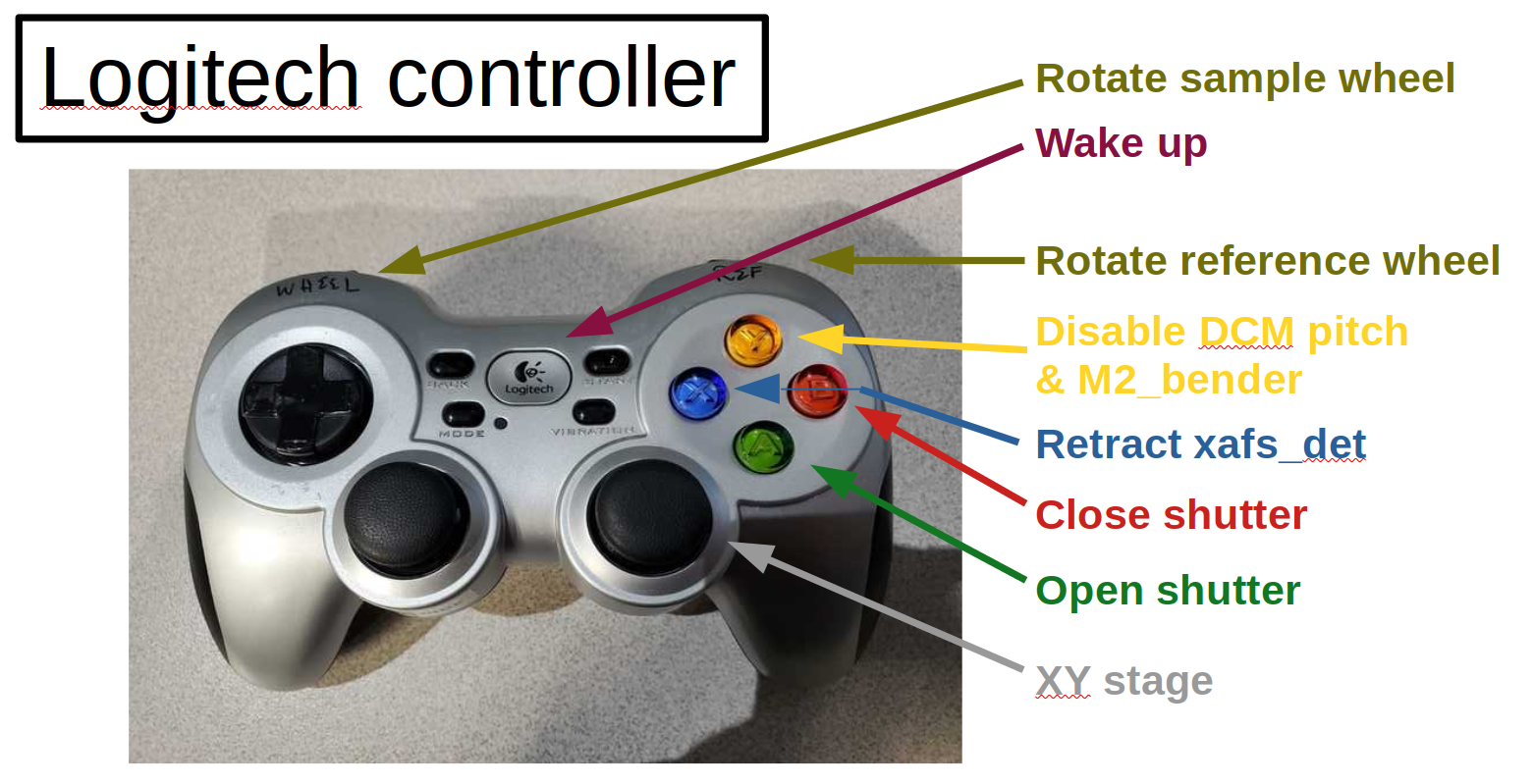
Todo
Explain how to configure buttons in CSS
Todo
Left joystick will be used for detector YZ. Not X!
E.11. M2 Bender#
The homing sequence on the bender (MC04, channel 6) seems to have the wrong parity. Instead of moving to the negative limit, it moves to the positive limit.
Rather than running the homing procedure, step to the negative limit.
This can be done via EPICS or by issuing the #6j- command in the
PEWIN terminal. Adam Young from FMBO indicated that the home marker
is about +6000 steps from the negative limit, so move there and zero
out the display – #6HMZ in PEWIN. This will leave the bender
reporting to EPICS that it is not homed, but it can be moved sensibly
to a bend value.
End station |
Bender position in steps |
|---|---|
XAS |
212225 |
XRD |
107240 |
E.12. MC09 patch panel#
Photo and explain…
E.13. Motor controllers#
This section is a big, long list of all the motor PV names at BMM.
Most motors have aliases. The alias is an alternate, easier-to-type name for the axis. These are equivalent:
caget XF:06BMA-OP{Mono:DCM1-Ax:Bragg}Mtr
caget xafs_bragg
Aliases work with most motor record fields, as well. The following are also equivalent:
caget XF:06BMA-OP{Mono:DCM1-Ax:Bragg}Mtr.VELO
caget xafs_bragg.VELO
The following tables give PV name and alias, a brief description of the purpose of the motor, the controller and location of that controller, and the channel number in the controller. A few abbreviations are used:
- us:
upstream
- ds:
downsteam
- ib:
inboard
- ob:
outboard
- para:
parallel
- perp:
perpendicular
E.13.1. Collimating mirror, M1#
PV |
alias |
Motor Description |
controller |
motor number |
|---|---|---|---|---|
XF:06BM-OP{Mir:M1-Ax:YU}Mtr |
m1_yu |
us jack |
MC01 (mezzanine) |
1 |
XF:06BM-OP{Mir:M1-Ax:YDO}Mtr |
m1_ydo |
ds, outboard jack |
MC01 (mezzanine) |
2 |
XF:06BM-OP{Mir:M1-Ax:YDI}Mtr |
m1_ydi |
ds, inboard jack |
MC01 (mezzanine) |
3 |
XF:06BM-OP{Mir:M1-Ax:XU}Mtr |
m1_xu |
us lateral |
MC01 (mezzanine) |
4 |
XF:06BM-OP{Mir:M1-Ax:XD}Mtr |
m1_xd |
ds lateral |
MC01 (mezzanine) |
5 |
E.13.2. Filters, DM1#
PV |
alias |
Motor Description |
controller |
motor number |
|---|---|---|---|---|
XF:06BMA-BI{Fltr:01-Ax:Y1}Mtr |
dm1_filters1 |
assembly #1 |
MC05 (RGA) |
6 |
XF:06BMA-BI{Fltr:01-Ax:Y2}Mtr |
dm1_filters2 |
assembly #2 |
MC05 (RGA) |
7 |
E.13.3. DCM#
PV |
alias |
Motor Description |
controller |
motor number |
|---|---|---|---|---|
XF:06BMA-OP{Mono:DCM1-Ax:Bragg}Mtr |
dcm_bragg |
DCM Bragg |
MC02 (RGA) |
1 |
XF:06BMA-OP{Mono:DCM1-Ax:Bragg2}Mtr |
dcm_bragg2 |
Bragg 2nd encoder |
MC02 (RGA) |
|
XF:06BMA-OP{Mono:DCM1-Ax:P2}Mtr |
dcm_pitch |
2nd xtal pitch |
MC02 (RGA) |
3 |
XF:06BMA-OP{Mono:DCM1-Ax:R2}Mtr |
dcm_roll |
2nd xtal roll |
MC02 (RGA) |
4 |
XF:06BMA-OP{Mono:DCM1-Ax:Per2}Mtr |
dcm_para |
2nd xtal perp |
MC02 (RGA) |
5 |
XF:06BMA-OP{Mono:DCM1-Ax:Par2}Mtr |
dcm_perp |
2nd xtal para |
MC02 (RGA) |
6 |
XF:06BMA-OP{Mono:DCM1-Ax:X}Mtr |
dcm_x |
lateral |
MC02 (RGA) |
7 |
XF:06BMA-OP{Mono:DCM1-Ax:Y}Mtr |
dcm_y |
vertical |
MC02 (RGA) |
8 |
E.13.4. Slits 2, DM2#
PV |
alias |
Motor Description |
controller |
motor number |
|---|---|---|---|---|
XF:06BMA-OP{Slt:01-Ax:O}Mtr |
dm2_slits_o |
outboard |
MC03 (RGA) |
1 |
XF:06BMA-OP{Slt:01-Ax:I}Mtr |
dm2_slits_i |
inboard |
MC03 (RGA) |
2 |
XF:06BMA-OP{Slt:01-Ax:T}Mtr |
dm2_slits_t |
top |
MC03 (RGA) |
3 |
XF:06BMA-OP{Slt:01-Ax:B}Mtr |
dm2_slits_b |
bottom |
MC03 (RGA) |
4 |
E.13.5. DM2 fluorescence screen#
PV |
alias |
Motor Description |
controller |
motor number |
|---|---|---|---|---|
XF:06BMA-BI{Diag:02-Ax:Y}Mtr |
dm2_fs |
vertical |
MC04 (RGA) |
7 |
E.13.6. Focusing mirror, M2#
PV |
alias |
Motor Description |
controller |
motor number |
|---|---|---|---|---|
XF:06BMA-OP{Mir:M2-Ax:YU}Mtr |
m2_yu |
us jack |
MC04 (RGA) |
1 |
XF:06BMA-OP{Mir:M2-Ax:YDO}Mtr |
m2_ydo |
ds, outboard jack |
MC04 (RGA) |
2 |
XF:06BMA-OP{Mir:M2-Ax:YDI}Mtr |
m2_ydi |
ds, inboard jack |
MC04 (RGA) |
3 |
XF:06BMA-OP{Mir:M2-Ax:XU}Mtr |
m2_xu |
us lateral |
MC04 (RGA) |
4 |
XF:06BMA-OP{Mir:M2-Ax:XD}Mtr |
m2_xd |
ds lateral |
MC04 (RGA) |
5 |
XF:06BMA-OP{Mir:M2-Ax:Bend}Mtr |
m2_bender |
bender |
MC04 (RGA) |
6 |
E.13.7. Harmonic rejection mirror, M3#
PV |
alias |
Motor Description |
controller |
motor number |
|---|---|---|---|---|
XF:06BMA-OP{Mir:M3-Ax:YU}Mtr |
m3_yu |
us jack |
MC05 (RGA) |
1 |
XF:06BMA-OP{Mir:M3-Ax:YDO}Mtr |
m3_ydo |
ds, outboard jack |
MC05 (RGA) |
2 |
XF:06BMA-OP{Mir:M3-Ax:YDI}Mtr |
m3_ydi |
ds, inboard jack |
MC05 (RGA) |
3 |
XF:06BMA-OP{Mir:M3-Ax:XU}Mtr |
m3_xu |
us lateral |
MC05 (RGA) |
4 |
XF:06BMA-OP{Mir:M3-Ax:XD}Mtr |
m3_xd |
ds lateral |
MC05 (RGA) |
5 |
E.13.8. Slits 3, DM3#
PV |
alias |
Motor Description |
controller |
motor number |
|---|---|---|---|---|
XF:06BM-BI{Slt:02-Ax:O}Mtr |
dm3_slits_o |
outboard |
MC06 (RGC1) |
5 |
XF:06BM-BI{Slt:02-Ax:I}Mtr |
dm3_slits_i |
inboard |
MC06 (RGC1) |
6 |
XF:06BM-BI{Slt:02-Ax:T}Mtr |
dm3_slits_t |
top |
MC06 (RGC1) |
7 |
XF:06BM-BI{Slt:02-Ax:B}Mtr |
dm3_slits_b |
bottom |
MC06 (RGC1) |
8 |
E.13.9. DM3#
PV |
alias |
Motor Description |
controller |
motor number |
|---|---|---|---|---|
XF:06BM-BI{FS:03-Ax:Y}Mtr |
dm3_fs |
fluorescent screen |
MC06 (RGC1) |
1 |
XF:06BM-BI{Fltr:01-Ax:Y}Mtr |
dm3_foils |
foils actuator |
MC06 (RGC1) |
4 |
XF:06BM-BI{BCT-Ax:Y}Mtr |
dm3_bct |
vertical stage |
MC06 (RGC1) |
3 |
XF:06BM-BI{BPM:1-Ax:Y}Mtr |
dm3_bpm |
NanoBPM |
MC06 (RGC1) |
2 |
E.13.10. XAFS Table#
PV |
alias |
Motor Description |
controller |
motor number |
|---|---|---|---|---|
XF:06BMA-BI{XAFS-Ax:Tbl_YU}Mtr |
xafs_yu |
xafs table y us |
MC07 (RGC1) |
1 |
XF:06BMA-BI{XAFS-Ax:Tbl_YDO}Mtr |
xafs_ydo |
xafs table y ds ob |
MC07 (RGC1) |
2 |
XF:06BMA-BI{XAFS-Ax:Tbl_YDI}Mtr |
xafs_ydi |
xafs table y ds ib |
MC07 (RGC1) |
3 |
XF:06BMA-BI{XAFS-Ax:Tbl_XU}Mtr |
xafs_xu |
xafs table x us |
MC07 (RGC1) |
4 |
XF:06BMA-BI{XAFS-Ax:Tbl_XD}Mtr |
xafs_detx |
xafs detector stage x |
MC07 (RGC1) |
5 |
Note
As part of a problem in 2024 involving a shorted motor coil on the
xafs_detx stage, the table horizontal motors got repurposed.
Axis 4 suffered a damaged amplifier. After replacing the motor,
the xafs_detx was placed on axis 5.
Axis 4 on MC07 is out of service. xafs_xu and xafs_xd have
been moved to MC09, axes 4 and 5
E.13.11. XAFS Stages#
E.13.11.1. XAFS stages on MC08#
PV |
alias |
Motor Description |
controller |
motor number |
|---|---|---|---|---|
XF:06BMA-BI{XAFS-Ax:LinY}Mtr |
xafs_liny |
xafs sample y |
MC08 (RGC1) |
1 |
XF:06BMA-BI{XAFS-Ax:LinX}Mtr |
xafs_linx |
xafs sample x |
MC08 (RGC1) |
2 |
XF:06BMA-BI{XAFS-Ax:LinS}Mtr |
xafs_det |
xafs reference stage |
MC08 (RGC1) |
3 |
XF:06BMA-BI{XAFS-Ax:LinXS}Mtr |
xafs_refy |
xafs reference y |
MC08 (RGC1) |
4 |
XF:06BMA-BI{XAFS-Ax:Pitch}Mtr |
xafs_pitch |
xafs pitch stage |
MC08 (RGC1) |
5 |
XF:06BMA-BI{XAFS-Ax:Roll}Mtr |
xafs_roll |
xafs tilt stage |
MC08 (RGC1) |
6 |
XF:06BMA-BI{XAFS-Ax:Ref}Mtr |
xafs_ref |
xafs reference wheel |
MC08 (RGC1) |
7 |
XF:06BMA-BI{XAFS-Ax:Mtr8}Mtr |
xafs_garot |
glancing rotation |
MC08 (RGC1) |
8 |
E.13.11.2. XAFS stages on MC07#
PV |
alias |
Motor Description |
controller |
motor number |
|---|---|---|---|---|
XF:06BMA-BI{XAFS-Ax:Tbl_RefX}Mtr |
xafs_refx |
xafs reference x |
MC07 (RGC1) |
6 |
XF:06BMA-BI{XAFS-Ax:Tbl_RotB}Mtr |
xafs_wheel |
xafs wheel stage |
MC07 (RGC1) |
7 |
XF:06BMA-BI{XAFS-Ax:Tbl_RotS}Mtr |
xafs_rots |
xafs small rot stage |
MC07 (RGC1) |
8 |
Note
In cabinet 4, there are two useful stages that are unused. One is a Huber theta/2theta stage. The other is a set of 4-axis slits.
E.13.11.3. XAFS stages on MC09#
PV |
alias |
Motor Description |
controller |
motor number |
|---|---|---|---|---|
XF:06BMA-BI{MC:09-Ax:1}Mtr |
xafs_dety |
xafs detector stage y |
MC09 (RGC1) |
1 |
XF:06BMA-BI{MC:09-Ax:2}Mtr |
xafs_detz |
xafs detector stage z |
MC09 (RGC1) |
2 |
XF:06BMA-BI{MC:09-Ax:3}Mtr |
xafs_spare |
spare xafs stage |
MC09 (RGC1) |
3 |
XF:06BMA-BI{MC:09-Ax:4}Mtr |
xafs_xu |
xafs detector stage y |
MC09 (RGC1) |
4 |
XF:06BMA-BI{MC:09-Ax:5}Mtr |
xafs_xd |
xafs detector stage y |
MC09 (RGC1) |
5 |
E.13.12. Gonimeter circles#
PV |
alias |
Motor Description |
controller |
motor number |
|---|---|---|---|---|
XF:06BM-ES{SixC-Ax:VTTH}Mtr |
6bm:sixc_vtth |
Vertical two theta |
MC11 (RGC2) |
1 |
XF:06BM-ES{SixC-Ax:VTH}Mtr |
6bm:sixc_vth |
Vertical theta |
MC11 (RGC2) |
2 |
XF:06BM-ES{SixC-Ax:CHI}Mtr |
6bm:sixc_chi |
Chi |
MC11 (RGC2) |
3 |
XF:06BM-ES{SixC-Ax:PHI}Mtr |
6bm:sixc_phi |
Phi |
MC11 (RGC2) |
4 |
XF:06BM-ES{SixC-Ax:HTH}Mtr |
6bm:sixc_hth |
Horizontal theta |
MC11 (RGC2) |
5 |
XF:06BM-ES{SixC-Ax:HTTH}Mtr |
6bm:sixc_htth |
Horizontal two theta |
MC11 (RGC2) |
6 |
XF:06BM-ES{SixC-Ax:ANAL}Mtr |
6bm:sixc_anal |
Analyzer |
MC11 (RGC2) |
7 |
XF:06BM-ES{SixC-Ax:DET}Mtr |
6bm:sixc_det |
Detector |
MC11 (RGC2) |
8 |
E.13.13. Goniometer motors#
PV |
alias |
Motor Description |
controller |
motor number |
|---|---|---|---|---|
XF:06BM-ES{SixC-Ax:DETHOR}Mtr |
6bm:sixc_det_h |
det horiz |
MC12 (RGC2) |
1 |
XF:06BM-ES{SixC-Ax:WHEEL1}Mtr |
6bm:sixc_wh1 |
wheel 1 |
MC12 (RGC2) |
2 |
XF:06BM-ES{SixC-Ax:WHEEL2}Mtr |
6bm:sixc_wh2 |
wheel 2 |
MC12 (RGC2) |
3 |
XF:06BM-ES{SixC-Ax:SAMX}Mtr |
6bm:sixc_samx |
sample X |
MC12 (RGC2) |
4 |
XF:06BM-ES{SixC-Ax:SAMY}Mtr |
6bm:sixc_samy |
sample Y |
MC12 (RGC2) |
5 |
XF:06BM-ES{SixC-Ax:SAMZ}Mtr |
6bm:sixc_samz |
sample Z |
MC12 (RGC2) |
6 |
XF:06BM-ES{SixC-Ax:Tbl_YD}Mtr |
6bm:sixc_tyd |
table Y ds |
MC12 (RGC2) |
7 |
XF:06BM-ES{SixC-Ax:Tbl_YUI}Mtr |
6bm:sixc_tyui |
table Y us ib |
MC12 (RGC2) |
8 |
E.13.14. Goniometer table#
PV |
alias |
Motor Description |
controller |
motor number |
|---|---|---|---|---|
XF:06BM-ES{SixC-Ax:Tbl_YUO}Mtr |
6bm:sixc_tyuo |
table Y us ob |
MC13 (RGC2) |
1 |
XF:06BM-ES{SixC-Ax:Tbl_XU}Mtr |
6bm:sixc_txu |
table X us |
MC13 (RGC2) |
2 |
XF:06BM-ES{SixC-Ax:Tbl_XD}Mtr |
6bm:sixc_txd |
table X ds |
MC13 (RGC2) |
3 |
XF:06BM-ES{SixC-Ax:Tbl_Z}Mtr |
6bm:sixc_tz |
table Z |
MC13 (RGC2) |
4 |
XF:06BM-ES{SixC-Ax:Slt1_T}Mtr |
6bm:sixc_slt1_t |
top slit |
MC13 (RGC2) |
5 |
XF:06BM-ES{SixC-Ax:Slt1_B}Mtr |
6bm:sixc_slt1_b |
bottom slit |
MC13 (RGC2) |
6 |
XF:06BM-ES{SixC-Ax:Slt1_I}Mtr |
6bm:sixc_slt1_i |
inboard slit |
MC13 (RGC2) |
7 |
XF:06BM-ES{SixC-Ax:Slt1_O}Mtr |
6bm:sixc_slt1_o |
outboard slit |
MC13 (RGC2) |
8 |
E.13.15. Shutters and screen#
PV |
alias |
Motor Description |
controller |
motor number |
|---|---|---|---|---|
XF:06BM-PPS{Sh:FE}Pos-Sts |
front end shutter |
PPS |
||
XF:06BM-PPS{Sh:A}Pos-Sts |
A hutch shutter |
PPS |
||
XF:06BMA-OP{FS:1}Pos-Sts |
fluorescent screen |
EPS |
E.13.16. Front-end slits#
PV |
alias |
Motor Description |
controller |
motor number |
|---|---|---|---|---|
FE:C06B-OP{Slt:12-Ax:X}size |
horizontal size |
geobrick (mezzanine) |
virtual |
|
FE:C06B-OP{Slt:12-Ax:X}center |
horizontal center |
geobrick (mezzanine) |
virtual |
|
FE:C06B-OP{Slt:12-Ax:Y}size |
vertical size |
geobrick (mezzanine) |
virtual |
|
FE:C06B-OP{Slt:12-Ax:Y}center |
vertical center |
geobrick (mezzanine) |
virtual |
|
FE:C06B-OP{Slt:1-Ax:Hrz}Mtr |
Slit 1 horizontal |
geobrick (mezzanine) |
||
FE:C06B-OP{Slt:1-Ax:Inc}Mtr |
Slit 1 incline |
geobrick (mezzanine) |
||
FE:C06B-OP{Slt:1-Ax:O}Mtr |
Slit 1 X outboard |
geobrick (mezzanine) |
||
FE:C06B-OP{Slt:1-Ax:T}Mtr |
Slit 1 Y top |
geobrick (mezzanine) |
||
FE:C06B-OP{Slt:2-Ax:Hrz}Mtr |
Slit 2 horizontal |
geobrick (mezzanine) |
||
FE:C06B-OP{Slt:2-Ax:Inc}Mtr |
Slit 2 incline |
geobrick (mezzanine) |
||
FE:C06B-OP{Slt:2-Ax:I}Mtr |
Slit 2 X inboard |
geobrick (mezzanine) |
||
FE:C06B-OP{Slt:2-Ax:B}Mtr |
Slit 2 Y bottom |
geobrick (mezzanine) |
E.14. Network configuration#
When introducing a new device to the beamline network:
Open a Jira ticket to request a new IP address and device name for DNS. As an example, a new Moxa terminal server was introduced. In the Jira ticket, we requested an IP address of 10.68.42.83 and a DNS entry of
xf06bm-tsrv13(full name:xf06bm-tsrv13.nsls2.bnl.local).In the case of a device that one in s series of similar devices, be sure that the name matches the similar devices and that the number is incremented. In the case of the new Moxa server, there are 12 others at the beamline. The numbers were incremented correctly for both the name and the IP address
Identify a port on one of the servers that is available and configured for the correct network. The networks are:
SCI (650): 10.68.40.xxx
CAM (651): 10.68.41.xxx
INST (652): 10.68.42.xxx
EPICS (653): 10.68.43.xxx
When configuring an individual device, here are the network configurations:
The gateway address on each network is
xz.yy.zz.2. For example, the gateway on the SCI network is 10.68.40.2.
The netmask is
255.255.255.0.
There are two DNS servers:
DNS1: 10.65.2.25
DNS2: 10.65.2.26
E.15. Pilatus 100K#
The Pilatus camserver is running on xf06bm-pilatus100k-651, which
is in the rack on wheels in the hutch. xf06bm-pilatus100k-651 is
10.68.41.29 and must be on the CAM network. The network cable
should be plugged into the port on the left on the back of the server
in the rack.
The IOC for the pilatus is running on xf06bm-ioc1. Note that this
is the only IOC running on xf06bm-ioc1.
E.15.1. Starting the system#
Start the NFS server on
xf06bm-pilatus100k-651. This can be done with the YAST GUI or by/etc/init.d/nfsserver restartMake sure that
/disk2onxf06bm-pilatus100k-651is mounted byxf06bm-ioc1at/disk2on that machine. That mount should happen at boot and be available as long as the Pilatus server is on the network.Start camserver on
xf06bm-pilatus100k-651. This is done in a terminal bystart-camserver.Start (or restart) the IOC on
xf06bm-ioc1by doingdzdo manage-iocs restart Pilatus100k
E.15.2. Overview of file saving#
The camserver writes tiff files to
/disk2onxf06bm-pilatus100k-651.That folder is NFS mounted on
xf06bm-ioc1as/disk2.The tiff and hdf5 AD plugins read individual images from that location and write tiff or hdf5 files to proposal directories.
In bsui, there are
pilatusandpilatus_tiffobjects. We normally usepilatus, which writes images to HDF5 files. Thepilatus_tiffobject is helpful for testing tiff file writing, which is used by IBM.
E.15.3. Configuring the tiff and pilatus AD plugins#
In CSS, configure the pilatus plugin parameters highlighted in yellow. Note that in Bluesky all of this is handled automagically by the ophyd object.
The file path must be set to /disk2.
The file name needs to be something, but is unimportant. TThese images will be copied by the IOC to the proposal folder or written by the IOC to an HDF5 file in the proposal folder.
Make sure the auto increment is set to Yes and that the filename
format is identical to the format used on the tiff plugin screen.
%s%s_%3.3d.tiff is a good choice.
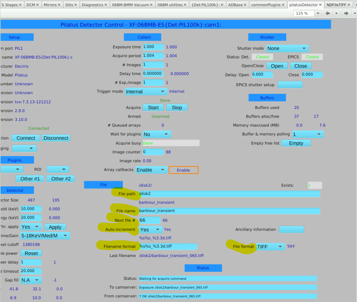
Fig. E.3 Pilatus plugin configuration screen#
On the tiff plugin configuration screen, several of the parameters must be set for any measurement.
The file path must be a location in the user’s proposal folder on shared storage. Thus, the path must be something like
/nsls2/data/bmm/proposals/2025-1/pass-123456/assets/pilatus100k-1
where you would replace the cycle number (2025-1 in this example)
with the current cycle number and the proposal number (123456 in
this example) with the user’s proposal number.
The IOC is only capable of writing to a location in the assets
folder. By good practice, it will write to the folder under
assets created for it. In the case of our Pilatus 100K, that
would be pilatus100k-1.
The filename format must be the same as on the pilatus plugin
screen. %s%s_%3.3d.tiff is a good choice.
The write mode must be stream and auto save must be
yes.
Much of this is handled in Bluesky by the ophyd object.
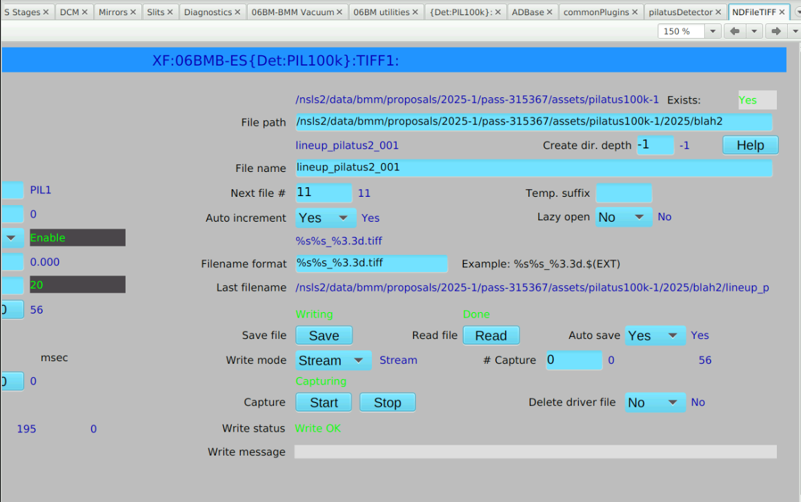
Fig. E.4 Tiff plugin configuration screen#
E.15.4. Setting ROIs#
To set and use ROIs, the ROI and Stats plugins must be enabled in the IOC. This can be done on the appropriate CSS screen, but all necessary plugins should become enabled when bsui starts and the pilatus object is instantiated.
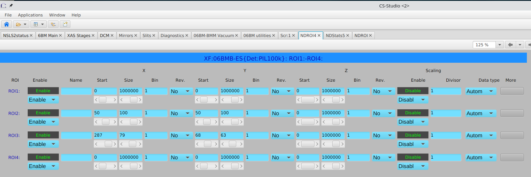
Fig. E.5 Initial configuration of the ROIs. In this example, ROIs 1 and 2 are being set to a subsection of the full image.#
To interact with the ROIs, their visualization must be enabled by clicking the corresponding buttons near the bottom of the CSS screen, as shown in the figure below. With those buttons clicked, the ROIs will be outlined on the image.
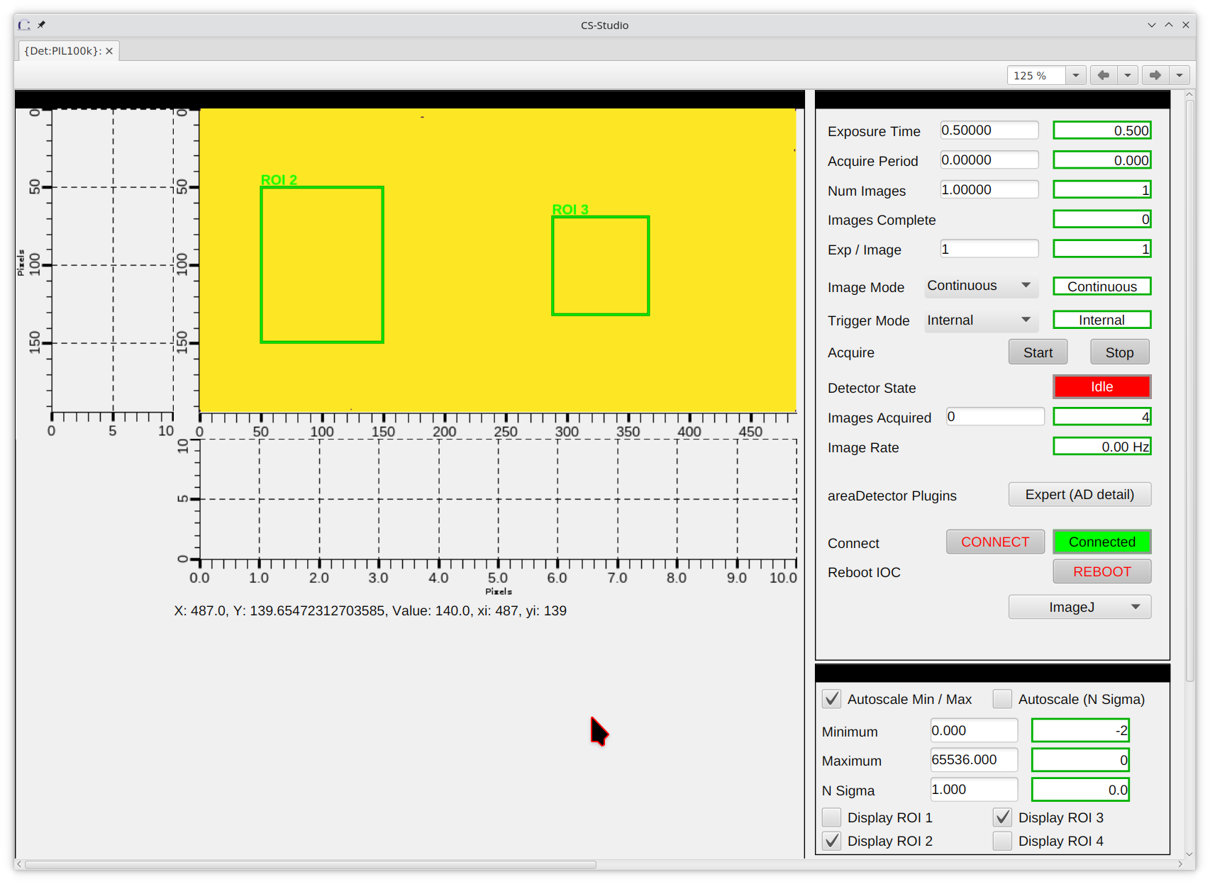
Fig. E.6 ROIs are displayed on top of the Pilatus image on the CSS screen.#
You can then click on the outline in the image to move or resize the ROI.
E.15.5. Measurements with the Pilatus in bluesky#
In bsui, the total-counts statistic (from the STATS plugin) for ROI2
is called diffuse and is hinted. This means that the total count
rate in the ROI will be recorded as a scalar in Tiled and that the
count rate will be reported in the best effort callback table printed
to the screen during the scan.
Similarly, the total count rate in ROI3 is called specular and is
hinted.
Those names are chosen as mnemonics for obvious parts of the scattering signal.
The header of the output XAFS scan file contains a metadata line identifying the location of the HDF5 file containing the Pilatus image stack for the scan.
E.15.6. Moving the detector between end stations#
The Pilatus and its rack typically live in the downstream, outboard corner of the hutch, near the XRD end station. For use on the XAS table, it is convenient to move the entire rack closer to the XAS table.
You will need to power down the server, the rack-mount computer in the rack. Then:
Unplug the power cables to the power strip
Disconnect the network cable from the back of the server
Valve off the GN2 supply at the wall, then disconnect the purple polyflow tube
Remove the green grounding line from the back wall.
Now the rack can be moved.
There is a power outlet and an GN2 supply fixture on the back wall, near the end of the XAS table. There is also a copper grounding strip near the floor that the green grounding cable can be clipped to. Also in that area is a blue network cable with a label that says “Pilatus @ XAS”. Plug that into the back of the server.
At the downstream network patch panel, unplug the network cable used when the rack is in its m=normal location. Search around for the other end of the “Pilatus @ XAS” cable and plu it into the patch panel.
Open flow of GN2 to the detector. Power up the server. Make sure the power switch for the detector is on.
Once you have logged into the server as the det user, open a
terminal window and do ../start_camserver to power up the
detector.
Make sure the time is correct on the Pilatus server
On xf06bm-ioc1, restart the Pilatus100K IOC with
dzdo manage-iocs restart Pilatus100K
You should be good to go.
E.15.7. Time synchronization#
Although the Pilatus server is configured to use an NTP server, it is (as of April 2025) unable to connect. As a result, the system time is likely to be quite wrong, possibly by several minutes.
The part of the IOC that moves images from /disk2 and saves them
on central storage either as HDF5 or tiff files requires that the
system times on the two machines be no more than a few seconds apart.
To synchronize the system time on xf06bm-pilatus100k-651 with
xf06bm-ioc1 do this:
On an
xf06bm-ioc1command line, enterdate. This will print a string like so:Wed Apr 2 07:35:49 PM EDT 2025
Copy that string.
On a command line on
xf06bm-pilatus100k-651, do this command:date -s "Wed Apr 2 07:35:49 PM EDT 2025"
replacing that string with the correct date and time from
xf06bm-ioc1.
That should do it.
E.16. Shelving Units and Cabinets#
Storage unit |
Short |
Purpose |
|---|---|---|
Shelf 1 |
S-1 |
Outside hutch – this n that |
Shelf 2 |
S-2 |
Outside hutch – BioLogic, Linkam, cat6 cables |
Shelf 3 |
S-3 |
Inside hutch – experiment supplies |
Cabinet 1 |
C-1 |
IBM storage |
Cabinet 2 |
C-2 |
IBM storage |
Cabinet 3 |
C-3 |
IBM storage |
Cabinet 4 |
C-4 |
Cryostat parts, mono & mirror parts, yield detector |
Cabinet 5 |
C-5 |
Samples, old stuff |
Cabinet 6 |
C-6 |
Old instruments, Poly-Flo tubing, misc. cables |
Cabinet 7 |
C-7 |
IBM storage |
Cabinet 8 |
C-8 |
Books, games, office supplies, USB & video cables |
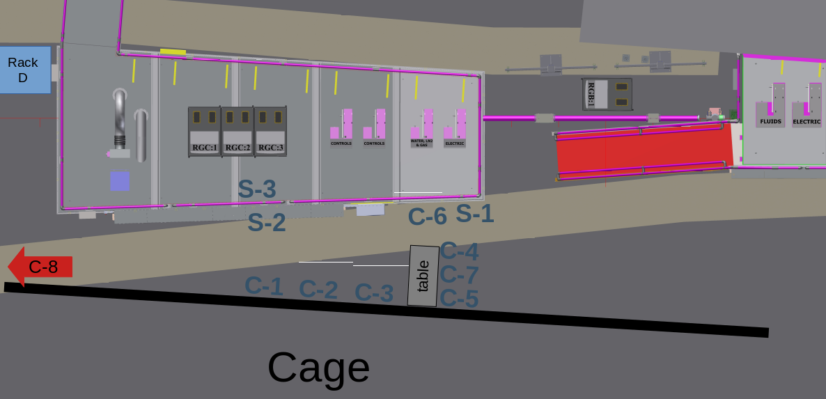
Fig. E.7 Shelf and cabinet locations#
E.17. Setting the table height#
This section outlines how the table height settings in the Modes lookup table were found.
For starters, the positions of dm3_bct in each of the modes were
established. This was done at 300 eV above the Pt L3 edge for modes
A, D, and E; the Fe K edge for mode C, and the Cr K edge for mode F.
Armed with set dm3_bct positions, the setup shown in
Figure E.8 was used to find the
positions of the XAFS table jacks.
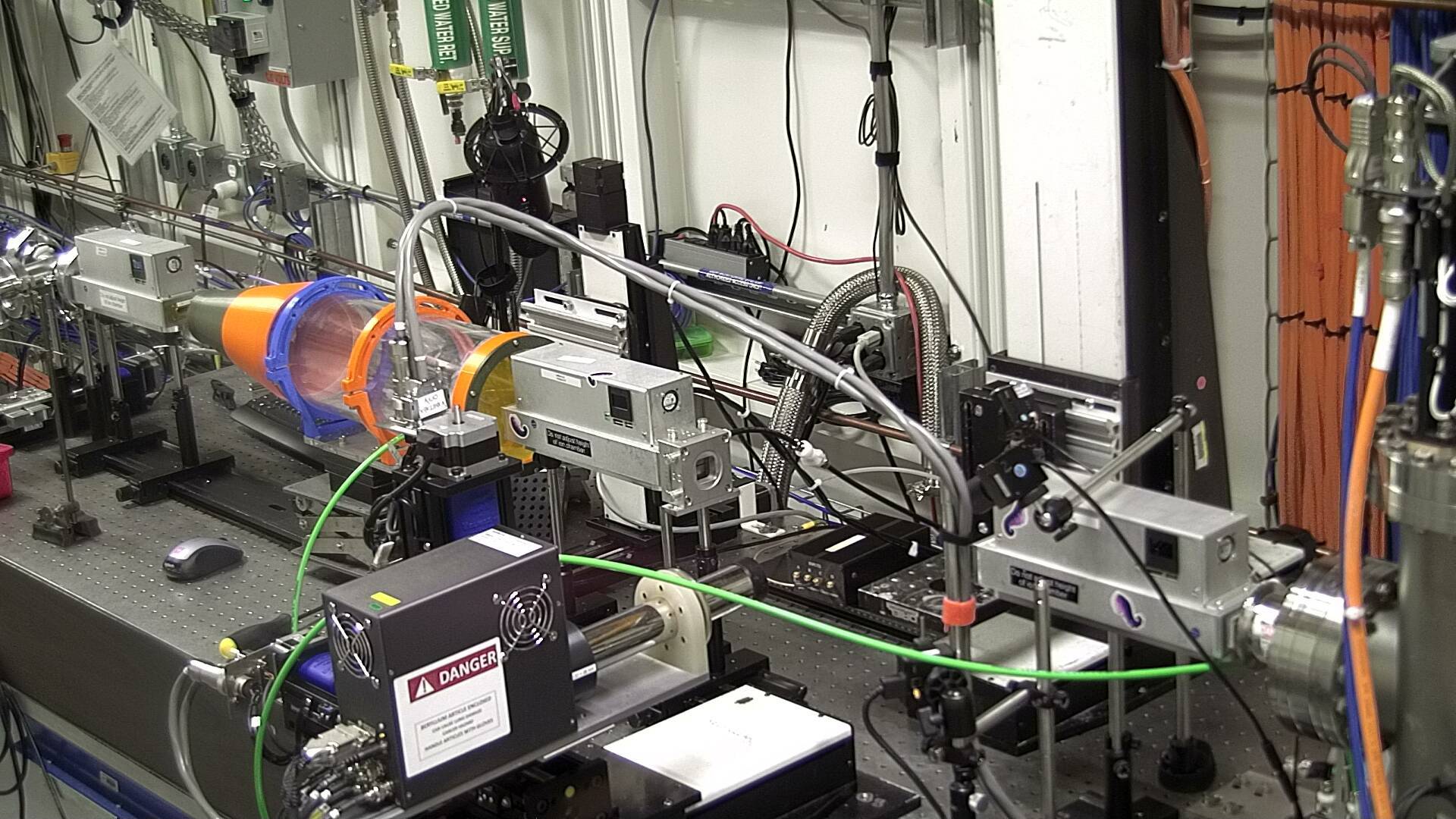
Fig. E.8 Table height measurement.#
The Ir detector is moved downstream of the two downstream jacks on the XAFS table. The It detector is moved downstream slightly to the other side of the upstream jack.
The manual slit assembly is mounted such that the opening is about 1/4 mm tall and centered in its housing. The height of the slit opening is carefully set to be at the same height as the centers of all the ion chambers.
With the slits in front of It, do a scan of the xafs_yu
motor looking at the signal on It. Move to the peak of this
scan.
With the slits in front of the Ir detector, adjust
xafs_ydo and xafs_ydi in unison to optimize the signal on Ir.
Move the slits back to the first position and verify that the
xafs_yu position still maximized the signal.
Record these positions in the Modes lookup table.
For the lower energy edges, insert the flight path borrowed from the XRD end station in between It and Ir. Run He through to reduce the attenuation of the beam at lower energies.
E.18. XAFS table holding current#
The controller axes for the vertical motion of the XAFS table were originally configured without a holding current. Over time, we noticed that the XAFS table would lose its position by a couple millimeters over the course of months. In an effort to combat this drift, a holding current was applied to those three axes in January 2025.
The three vertical table axes are channels 1, 2, and 3 on MC07, which is a Geobrick Power PMAC.
This turned out to be a little complicated. It turns out that the holding current is controlled by PLC7 in the Geobrick Power PMAC controllers. That PLC uses several P-variables on the controller, as explained in the comment block at the top of the PLC code. (Note: that link requires logging onto the BNL VPN.)
Here is the text of that comment:
; Note1: Geobrick controllers when killed effectively short the motor cables together providing an
; brake due to back EMF when the motor is rotated. Most axis can be safely killed without losing
; position, this is certainly the case for most lead screw drives (ball screws may require a
; holding current).
;
; Note2: When using this PLC make sure the standard kill PLC (usually PLC7, sometimes PLC3) is removed from the geobrick.
;
; Settings:
; P701-P708
;   Define timeout period in milliseconds after which the axis will be powered
;   down provided it has been idle for the whole period (note clock resolution below).
;   Set to zero to leave the amp powered continously.
;   Set to one for (almost) immediate power down on motor stop.
;   Set to number of milliseconds for delayed power down after motor stops.
;   Typically this should be set to a few seconds.
; P733-740
;   Drive current & percentage for each axis.
;   Set to zero for axis that are to be killed or if controller is not a geobrick (i.e. does not support Ixx77 amp current).
;   For axis requiring a reduced holding current this contains ' normal_drive_current * 100 + power_down_percentage '
;   Note the drive current is defined in milliamps.
;   e.g. For motor axis 1 with 2000 milliamp drive current and 33% holding
;   current define P733 as 200033
OK! So how do we make all that happen? Firing up PEWIN on the Windows laptop connected to MC07, open the windows for viewing the I-variables and the P-variables.
All the relevant parameters were set in PEWIN as shown in the figures below. MC07 was then power cycled. After power cycling, those three axes have a good strong holding current in place.
A holding current of 30% of drive current was selected because the table is rather heavy. Jakub Wlodek’s suggestion was “I usually go with 10% unless it is lifting something heavy”.
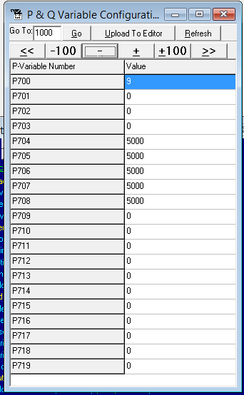
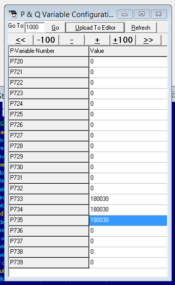
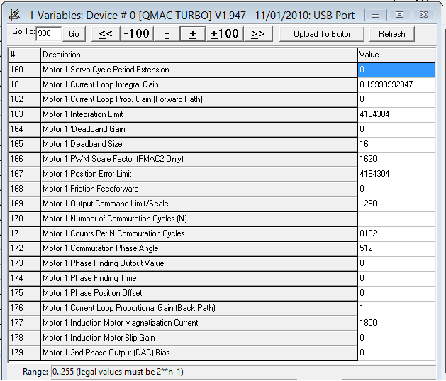
Fig. E.9 (Left) The P-variables window showing parameters P701-708. The values P701, P702, and P703 are for axes 1, 2, and 3. The value of 5000 – disable amplifier 5000 ms after a move – are changed to the value of 0, thus leaving the amplifiers enabled. (Middle) The P-variables window showing parameters P733-740. The values P733, P734, and P735 are for axes 1, 2, and 3. These are set to supply a holding current of 30% of the drive current using the specified formula. (Right) The I-variables window showing the relevant parameter for axis 1. The I177 parameters is set to 1800 mA, as are I277 and I377. This value was used to compute the value of the P733 - 735 parameters.#
Note
To effect this change in the holding current, it seems you have to press the “Upload To Editor” button at the top of the P-variables window. In truth, I am not 100% sure about that step, but it seems as though the changes to the P-variables and the subsequent changes to the PLC do not take effect without that step.
Maybe this could be revisited by someone with more knowledge of how PEWIN and the Power PMAC actually work…
E.19. Vortex pressure#
Using a probe to measure the voltage on the IP port of the Vortex ME4. This reading will tell you the internal pressure according to the table in the snapshot below.
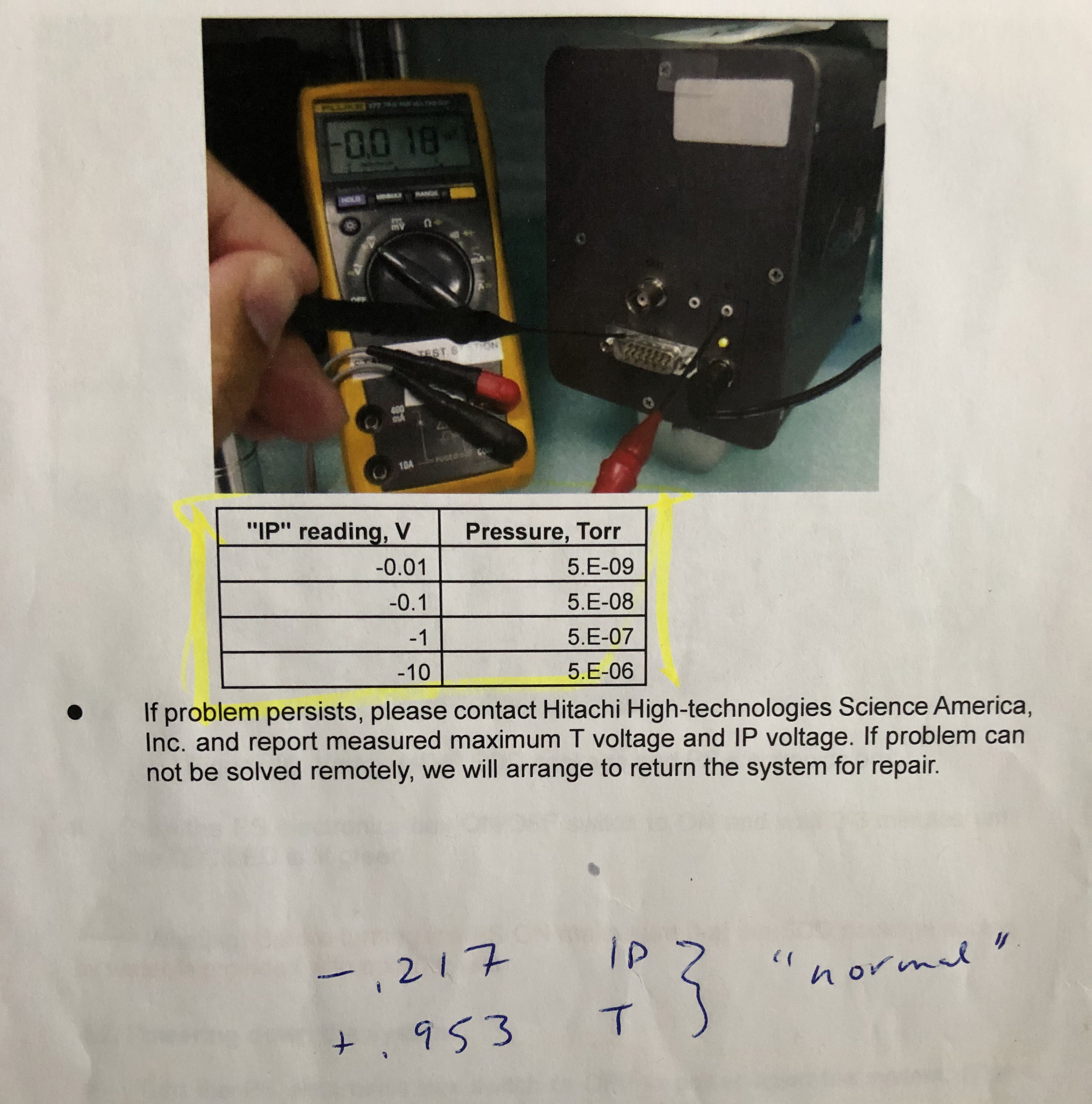
IP reading (Voltage) |
Pressure |
|---|---|
-0.01 |
5E-9 |
-0.1 |
5E-8 |
-1 |
5E-7 |
-10 |
5E-6 |
Note that the voltages are positive on the 7-element and negative on the 4-element.
Temperature reading on the 4-element should be 1.5 V when the TEC is at proper temperature. Temperature should be 0.6 V on the 7-element detector.
Vortex SDD manual (link to copy at APS detector pool).
There is a copy of the Vortex manual at BMM. Look in
/nsls2/data3/bmm/legacy/products/ME7/, the file is called
Vtx-Multi-El User Manual Rev 15.0_Oct 16, 2023.pdf.
E.20. Zoom calls in the hutch#
xf06bm-ws5 (10.68.40.225) is the System 76 Meerkat mounted on
the inboard wall of the end station behind the XAS table and just
below the lower, right corner of the screen. This machine is intended
to allow the users in the hutch to join a Zoom chat from within the
hutch. This allows staff to provide user support from home.
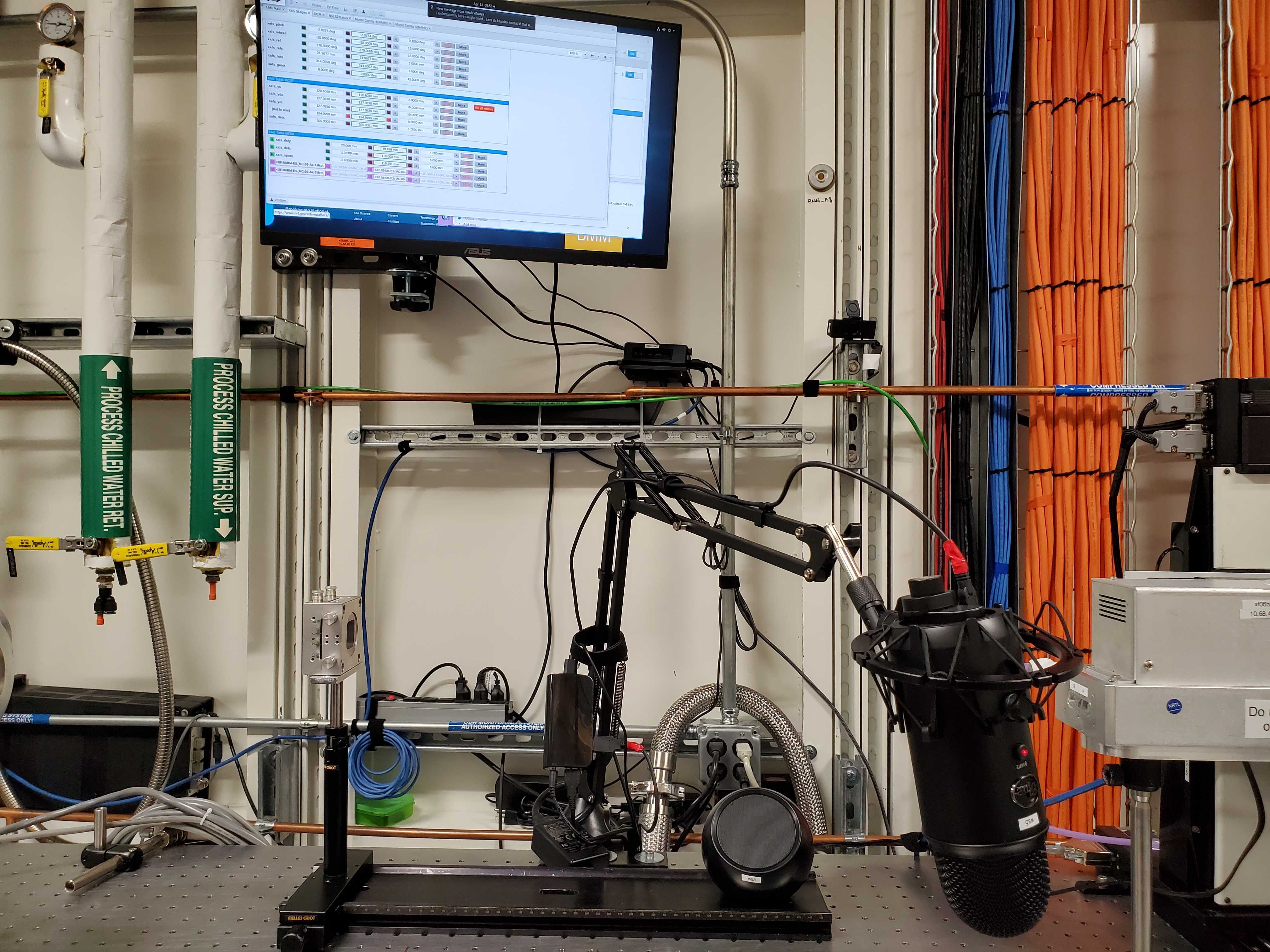
There are a number of peripherals attached to xf06bm-ws5:
A wireless mouse and keyboard clearly labeled as being for this computer. These are normally sitting near the end of the XAS table.
A screen. This is the screen mounted in the back wall of the hutch using an articulated arm.
A reasonably loud speaker. This is the black ball-shaped item which usually sits underneath the Ir chamber. Could be louder…
A good microphone. This is the Blue Yeti on a boom above the Ir chamber. It has good noise cancellation so the din from the XSpress3 should not effect voice quality. It is, however, important that the speaker face the microphone when speaking.
A decent camera. This is the Nexigo mounted on the inboard wall to the right of the screen.
While these devices are all connected to xf06bm-ws5 and powered
on, there are no long running processes that connect to the camera or
microphone. You are not being spied upon while in the hutch – unless
you are on a Zoom call, in which case the Zoom session will be on
screen.
xf06bm-ws5 is available via Guacamole. When needed for remote
support, Bruce will initiate the Zoom call and have the hutch computer
join in.