
5. Beamline instrumentation#
This section provides a brief overview of the instrumentation available for various kinds of routine and in situ experiments.
If you have questions about any of these tools or wish to pursue other experimental options, contact the beamline staff.
5.1. Fluorescence detectors#
The standard fluorescence detector at BMM is a seven element silicon drift detector with an Xspress3 readout. This normally sits on a linear stage so that distance to the sample can be user-controlled and incorporated into beamline automation (Section 11).
We also have a single element silicon drift detector which is useful in certain situations. If your experimental setup requires placing the detector in an unusual orientation, the single element detector can be used. Unlike the 7-element detector, the single element is not required to remain in an upright orientation during operation. While the single element detector sees fewer photons, this versatility of setup is occasionally very helpful.
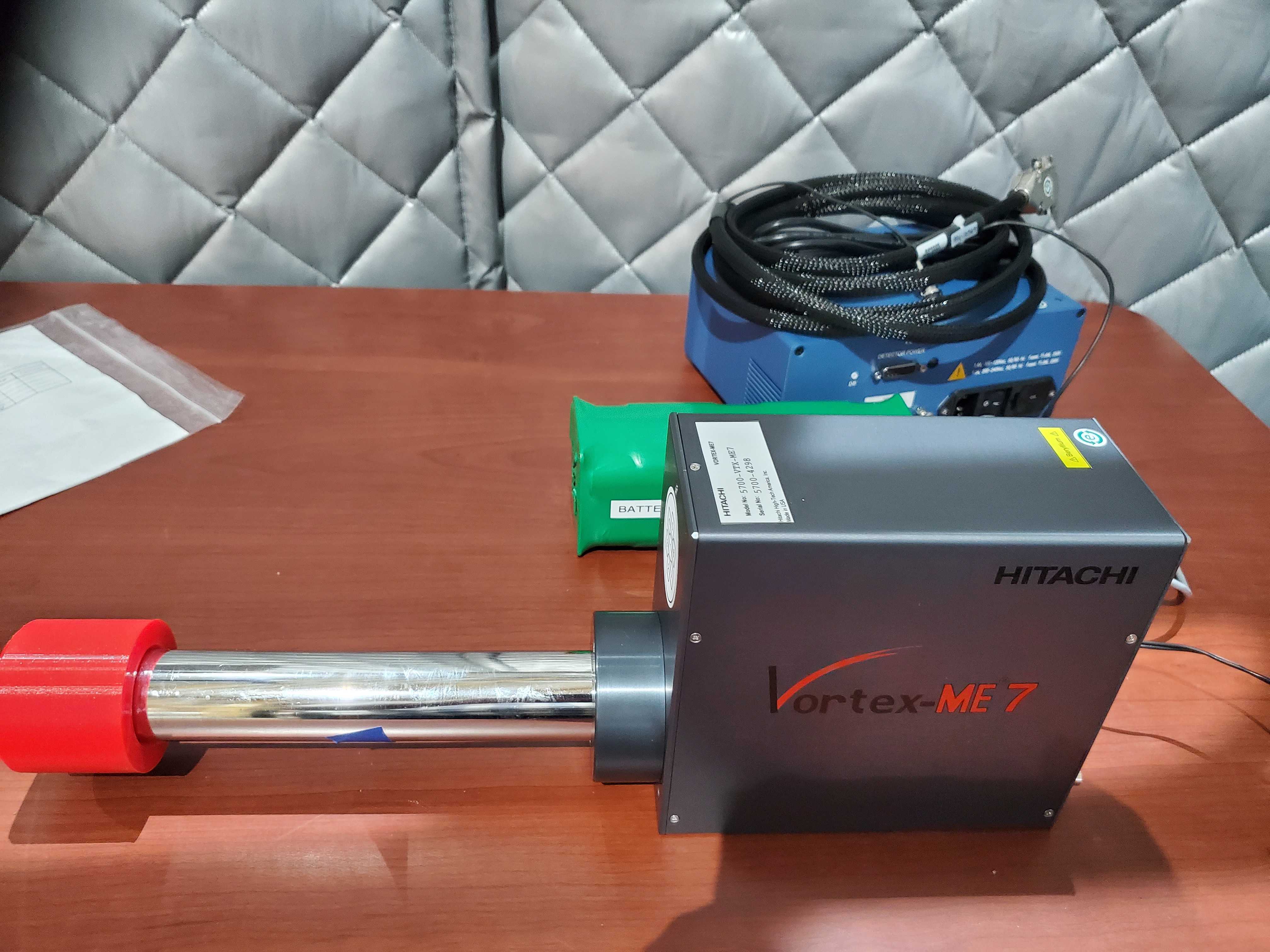
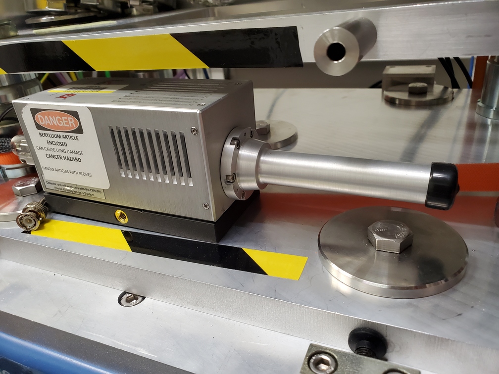
Fig. 5.1 (Left) Seven element silicon drift detector. (Right) One element silicon drift detector.#
BMM has an elderly 4-element SDD as a back-up detector.
The 7-element detector sits on an XYZ stage for alignment with the beam.
axis |
purpose |
|---|---|
|
proximity to sample |
|
vertical position |
|
uypstream/downstream position |
The xafs_detx stage is fully retracted at a position of 205. The
closest position is often something close to 0, but that depends on
the details of the sample stage and will be set as a soft limit at the
beginning of an experiment. To
fully retract the stage, do
RE(mv(xafs_detx, 205))
The xafs_dety stage is normally at position 0. Position 0 is
chosen to have the beam at the height of the center element of the
detector. When using the glancing angle stage (Section 5.7) in the parallel orientation, move xafs_dety
to position 20.
RE(mv(xafs_dety, 20))
The xafs_detz stage moves the detector upstream or downstream
according to the details of the sample mount. It is usually good
enough to align this by eye. A more careful alignment can be made
with a linescan (Section 8):
RE(linescan(xafs_detz, 'if', -10, 10, 51))
Note that this scan will optimize the signal in the ROI, but may not serve to minimize elastic scattering or to balance signal between the sides of the detector.
5.2. Electron yield detector#
Todo
Document this!
Todo
Better scheme in Bluesky for specifying that the yield detector is in use and that its signal should be plotted in real time.
5.3. Area detector#
An older model of the Pilatus 100K is available.
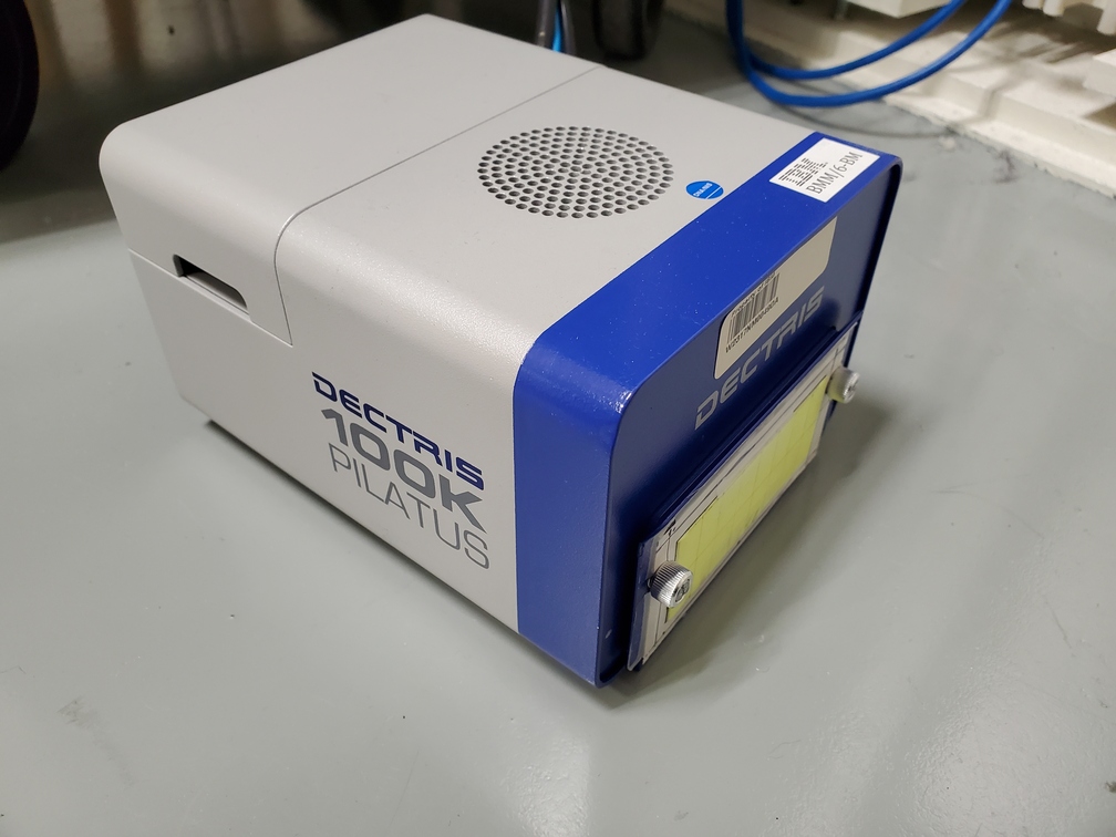
Fig. 5.2 Dectris Pilatus 100K#
Please note:
BMM offers only limited integration of data output into the XAS end station workflow.
BMM has limited options for mounting and integrating the Pilatus into your experiments.
This Pilatus has a rather small detection area and a rather large pixel size (about 170 microns).
BMM does not currently have access to a larger/better/faster detector.
Using CHIPS Act funding, we are in the process of procuring a new large area detector for use with the XRD end station. This detector will eventually become available for experiments at the XAS end station, perhaps by 2026.
5.4. Sample wheel#
At BMM, the standard ex situ sample stage is a laser-cut plastic disk. The disk has 24 or 48 slots cut from the disk. These are the sample positions.
This disk is mounted on a rotation stage. The slots are 15 degrees apart, so moving from sample to sample only involves moving through a known rotation angle.
The rotation stage is mounted on the XY stage, allowing alignment of the sample holder to the incident beam.
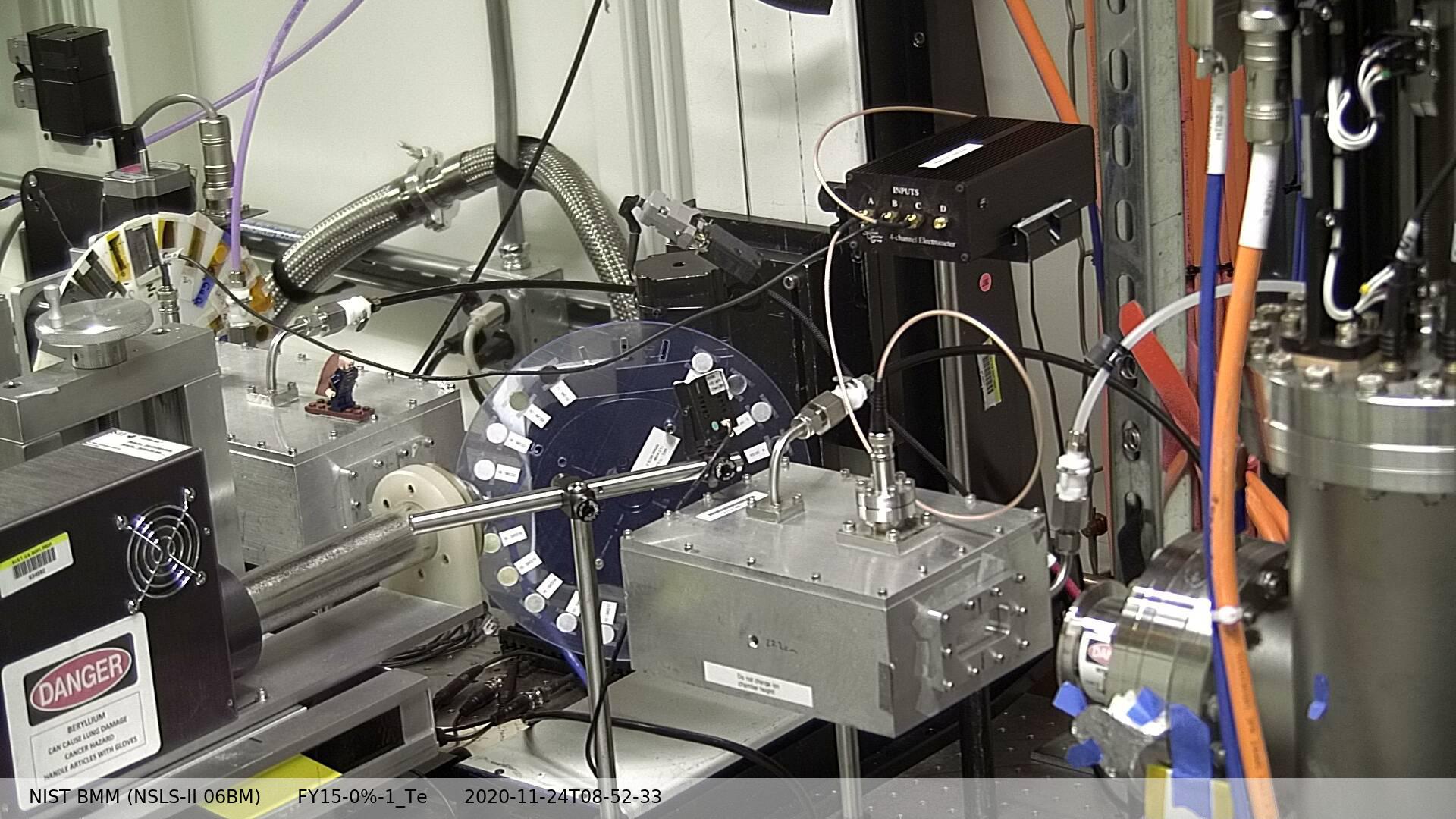
Fig. 5.3 The standard ex situ sample holder is a plastic disk with slots for the sample positions.#
Here are photos of some of the sample holder options. There are designs which use slots or circles for the sample position. The circular holes are 13 mm, which is a common size for a pellet press. 13 mm pellets can usually slip snugly into those holes.
Samples can be packed into the slots or holes. More commonly, samples are prepared in some manner and affixed to the front of the sample holder with tape.
There is also a design which is, essentially, a normal disk cut in half. That one holds fewer samples, but is easier to load and unload from a glove box during sample preparation.
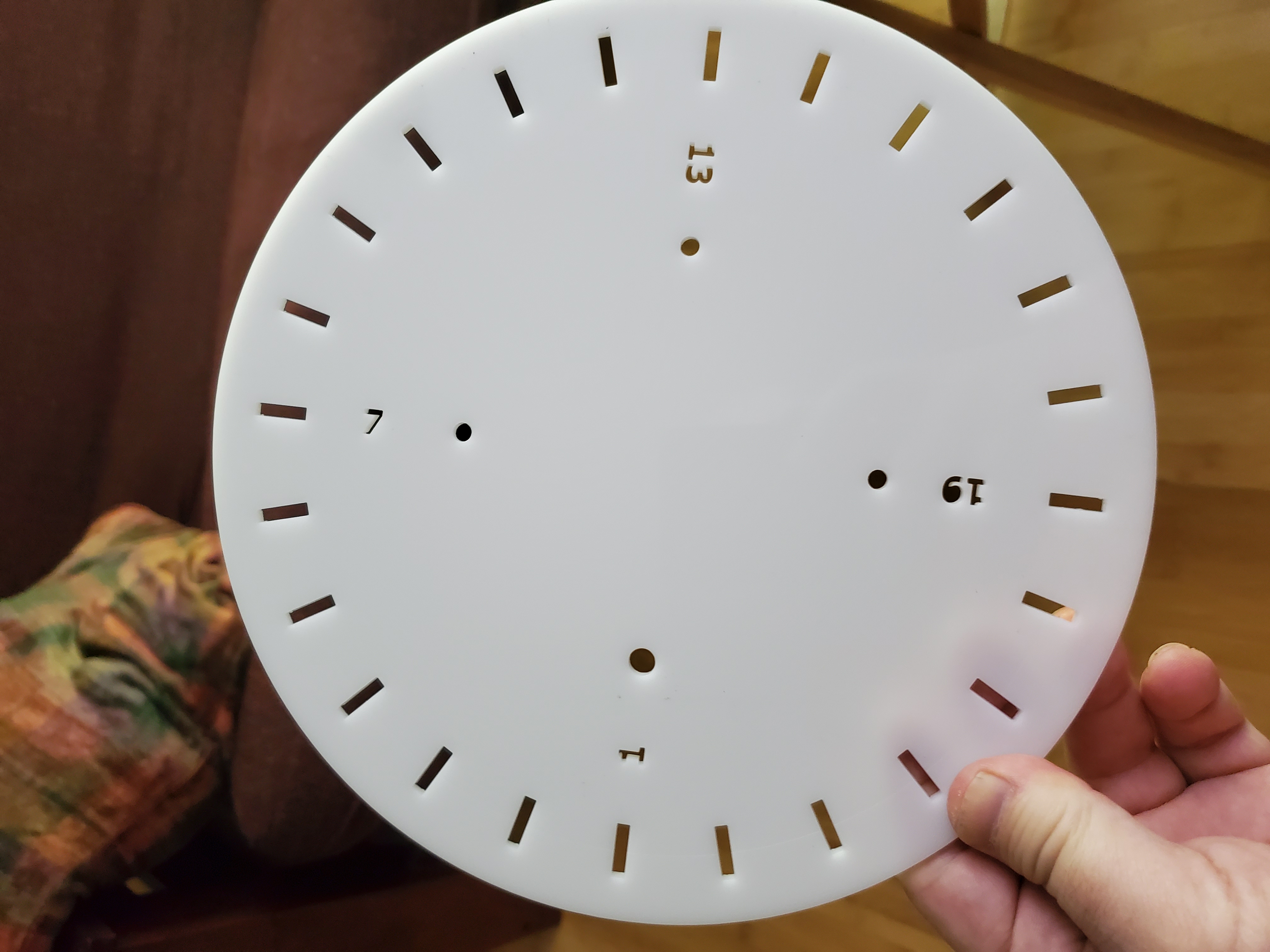
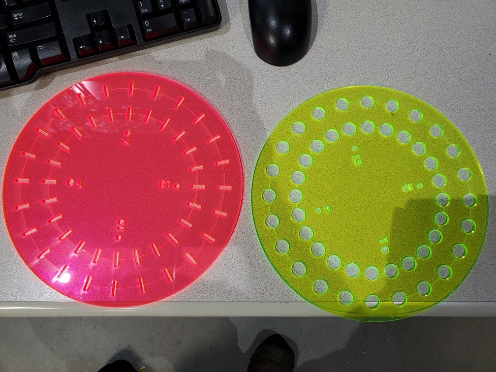
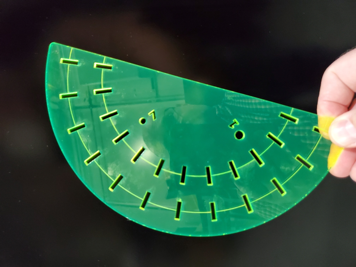
Fig. 5.4 (Left) A single-ring sample wheel with 24 sample positions. (Center) Double-ring sample wheels with 48 sample positions. For both styles, there are options with 13mm x 3 mm slots or 13mm diameter holes. (Right) A half wheel suitable for loading in a glove box.#
We consider these ex situ holders to be consumable items. We will happily mail several of them to you prior to your experiment so that you can arrive with samples pre-mounted and ready to be measured. You may keep the sample holders to use again the next time you visit BMM.
5.5. Electrochemistry#
At BMM, we have a BioLogic VSP-300 Potentiostat which is available for all manner of electrochemistry experimentation. This is a 6 channel model, allowing you to prep samples during measurements or to run multiple electrochemistry experiments in parallel, moving those cells into and out of the beam.
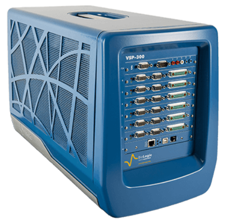
Fig. 5.5 The BioLogic VSP-300 Potentiostat#
We run the vendor-supplied control software on a Windows 10 instance
running in a virtual container. Your electrochemical data will be
saved to the assets/vsp300-1/ folder in your proposal
folder (Section 4).
Note
We do not, at this time, have EPICS-level control of the potentiostat. This limits the level of automation and integration with the rest of the beamline.
DSSI has implemented external triggering and collection of current and voltage using the Quantum Detectors PandABox. This may become available to BMM users sometime in 2025.
BMM does not provide electrochemical cells. The user is expected to bring their own cells. Ideally, the electrochemistry has been tested in the cells intended for use at the beamline and are known to produce reliable electrochemical results.
5.6. Temperature control#
BMM has two options for experiments at elevated or reduced temperature.
5.6.1. Linkam stage#
The Linkam stage has LN2 flow for cooling a sample down to 77K and a resistive heater to go up to 600C. The volume inside can be pumped or exposed to flowing gas. The sample stage at the center is modified to have a 3mm diameter hole for transmission XAFS.
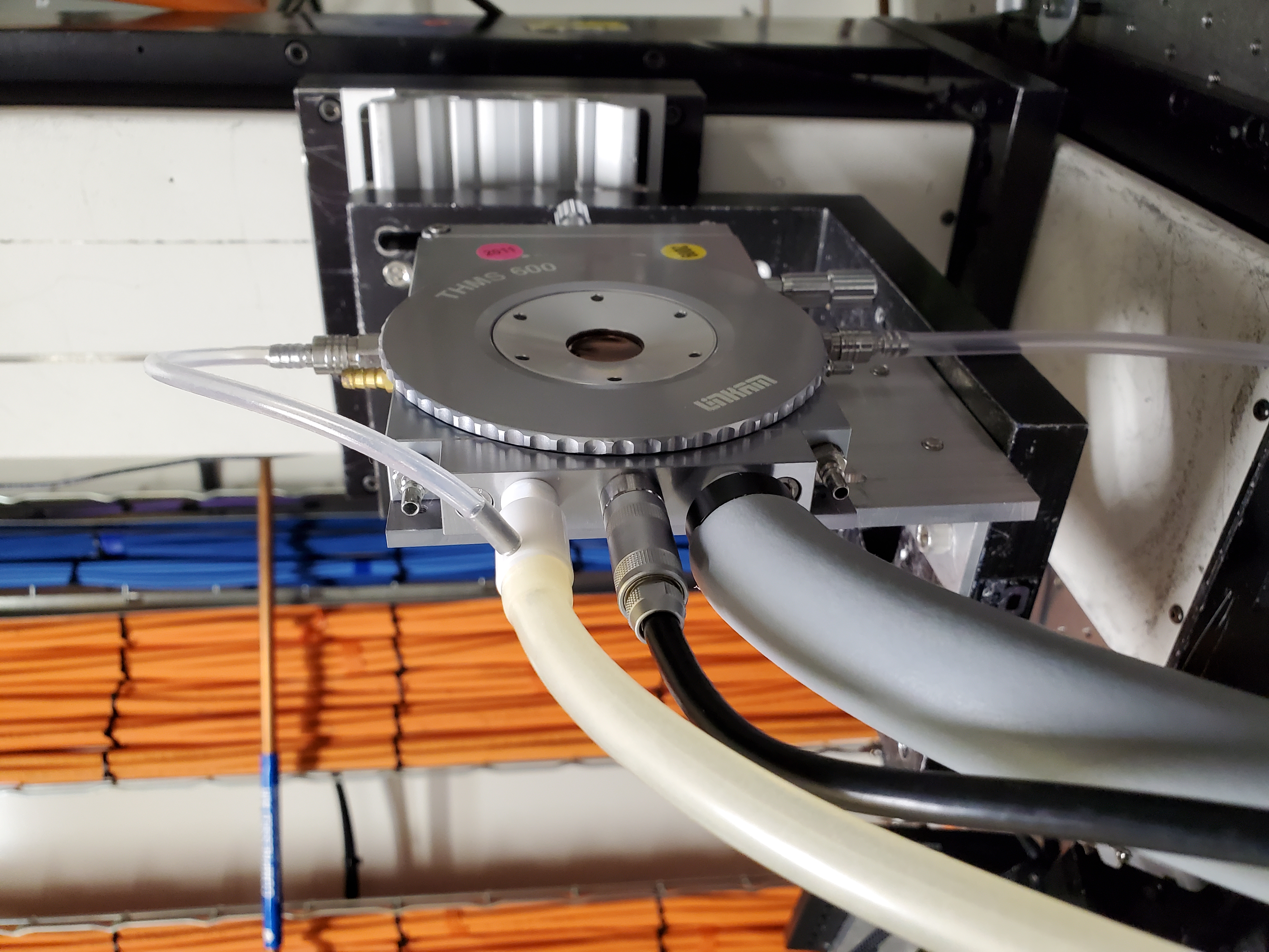
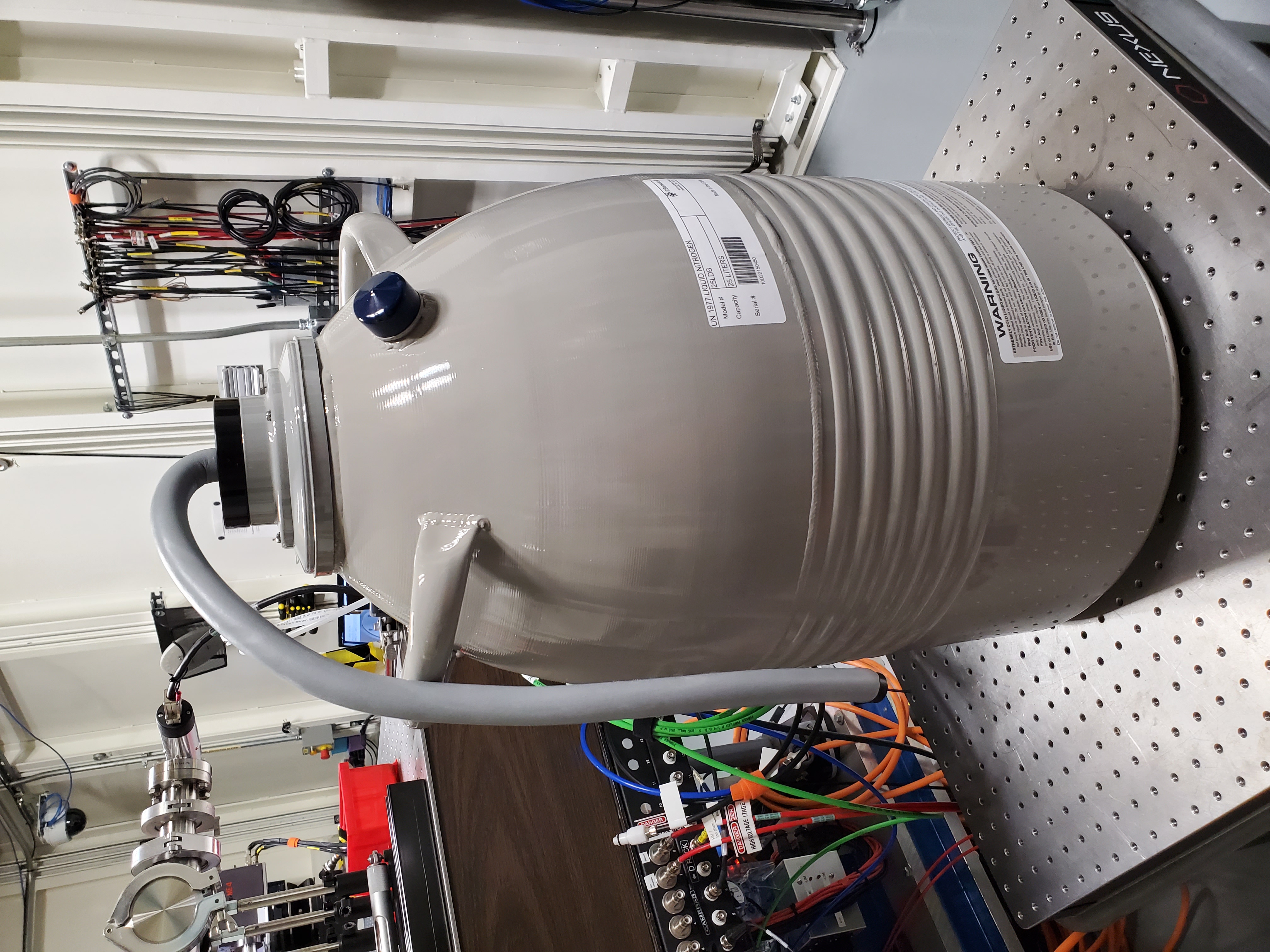
Fig. 5.6 (Left) The Linkham stage mounted for transmission on the sample stage. (Right) The 25 L dewar used for cooling the Linkam stage.#
BMM has two dewars for use with the Linkam. The 2 L dewar has enough capacity for about 2 hours of measurement. The 25 L dewar runs for about 14 hours and is the standard choice. The advantage of the smaller dewar is that it is smaller and might be needed for complicated setups were space is at a premium.
Extensive automation (Section 11.4) is available for the Linkam stage.
5.6.2. Displex Cryostat#
BMM also has a helium compression cryostat capable of reducing temperature at the sample to around 10K and with a resistive heater allowing a sample temperature range of 10K to about 400K.
This Displex model is designed for low-vibration applications. as a result, it is a bit slow to cool down, requiring about 2 hours to get to 10K from room temperature. Sample changes are a bit laborious due to the construction of the vacuum shroud.
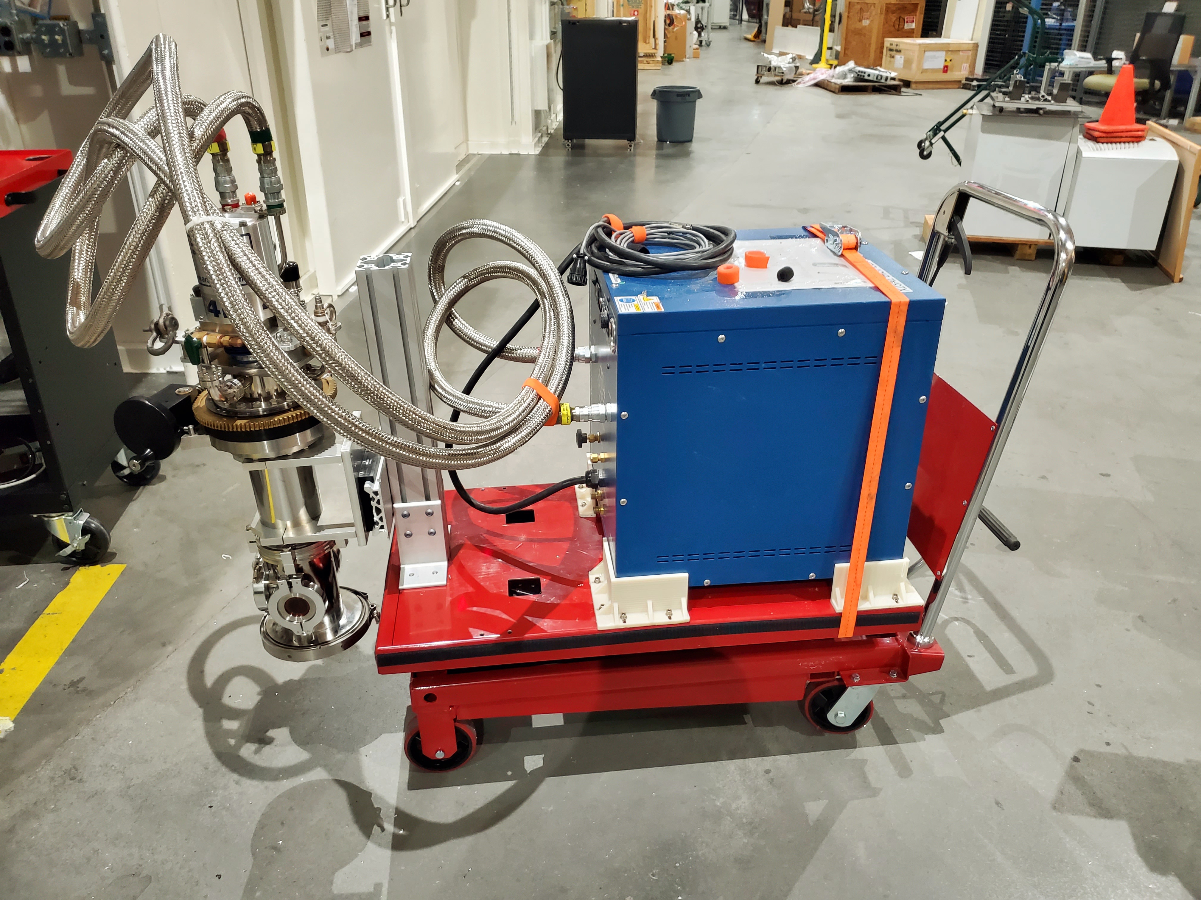
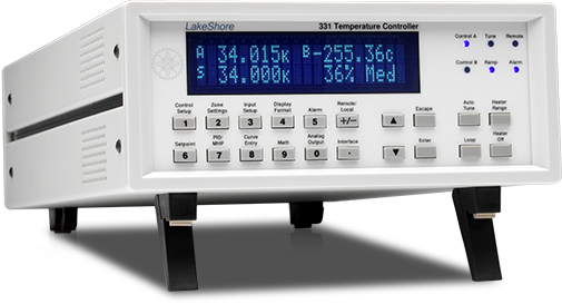
Fig. 5.7 (Left) The Displex cryostat and it’s compressor. (Right) The LakeShore 331 controller, used to control temperature for the cryostat shown to the left.#
Extensive automation (Section 11.5) is available for the Displex using the LakeShore 331 temperature controller..
5.7. Glancing angle and thin film stage#
We use this glancing angle stage for high-throughput studies of thin film and other flat samples. The apparatus shown below rests on a rotation stage for moving up to 8 samples into and out of the beam. The rotation stage sits on a tilt stage, allowing fine control of the incident angle. Each sample position is a spinner, which is used to suppress diffraction from the substrate.
In most cases, sample translation and sample alignment is fully automated (Section 11.6)
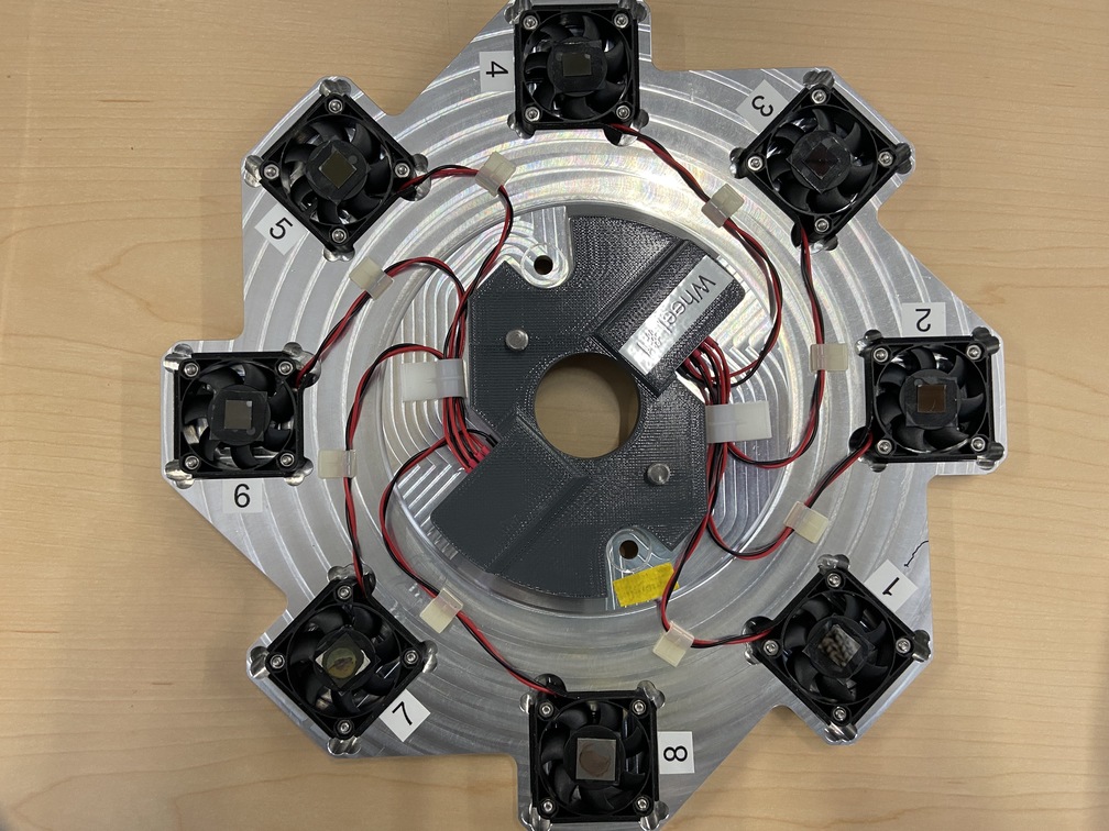
Fig. 5.8 The glancing angle stage with 8 sample positions.#
While a standing wave experiment might be feasible at BMM, the much more typical application is a simple glancing angle measurement in which the point of the shallow angle is to spread the beam out over the full length of the sample. This significantly increases the number of atoms involved in the measurement.
5.8. Tilt and rotation stages#
Also available are a Huber pitch and roll stage in the form of an Eulerian cradle and a compact rotary stage.
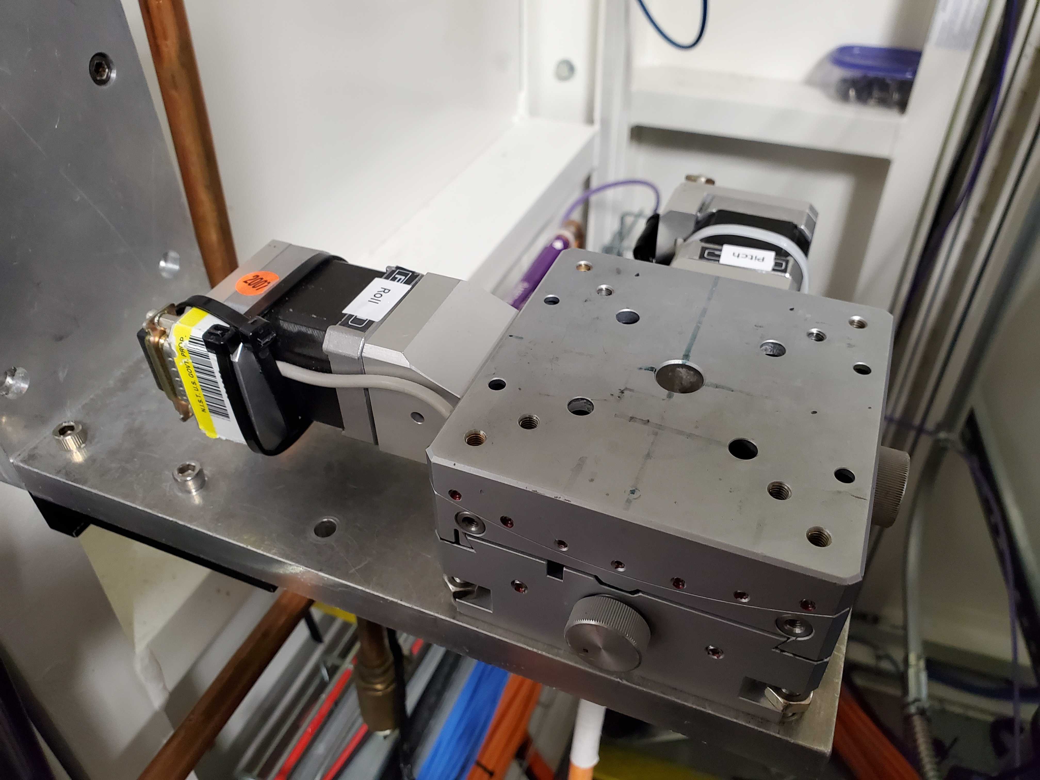
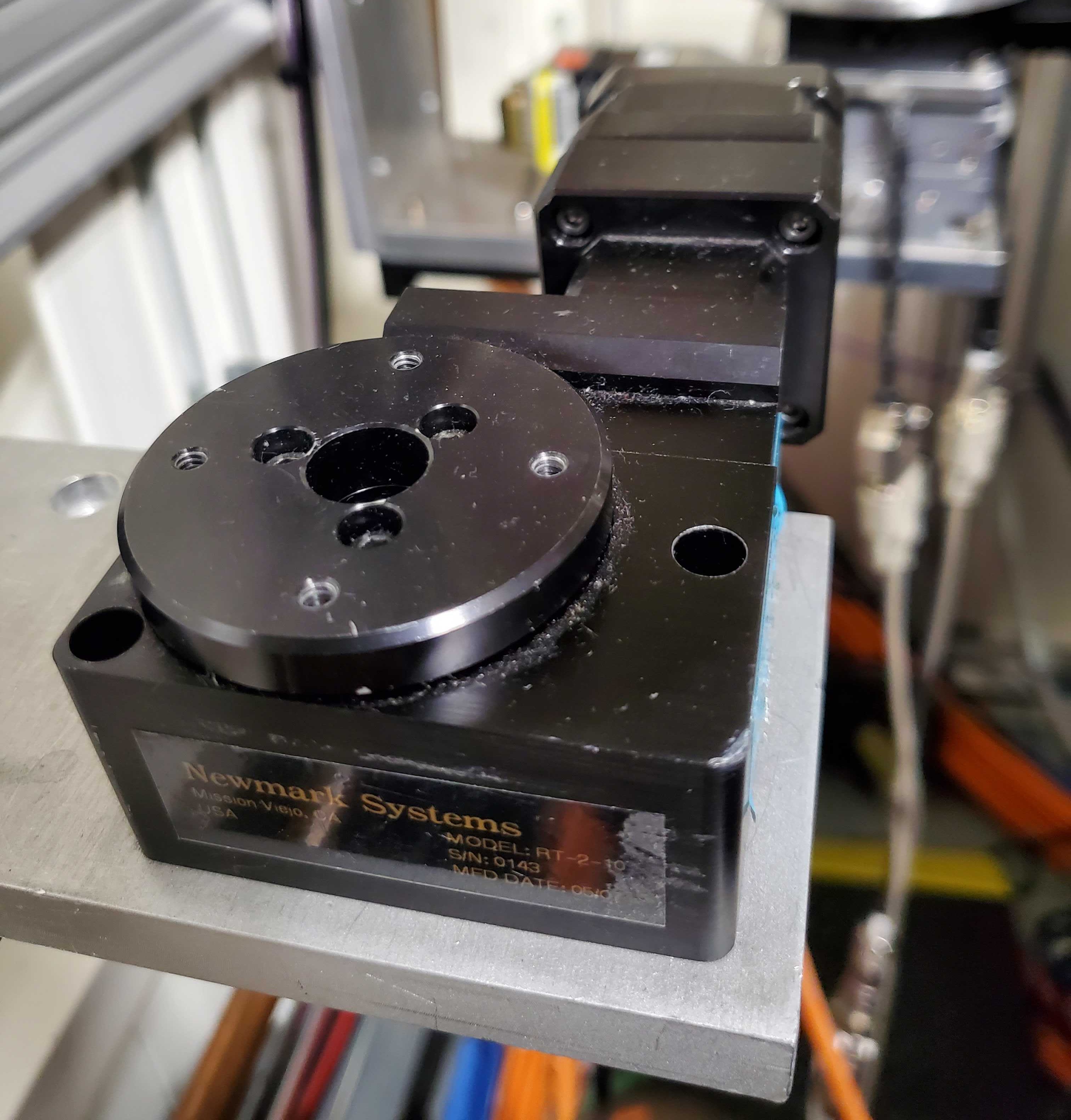
Fig. 5.9 (Left) The pitch and roll stage. (Right) The small rotation stage#
Here are mechanical drawings, including bolt hole patterns. Consult these if designing an instrument intended to be mounted for rotation, pitch, or roll.
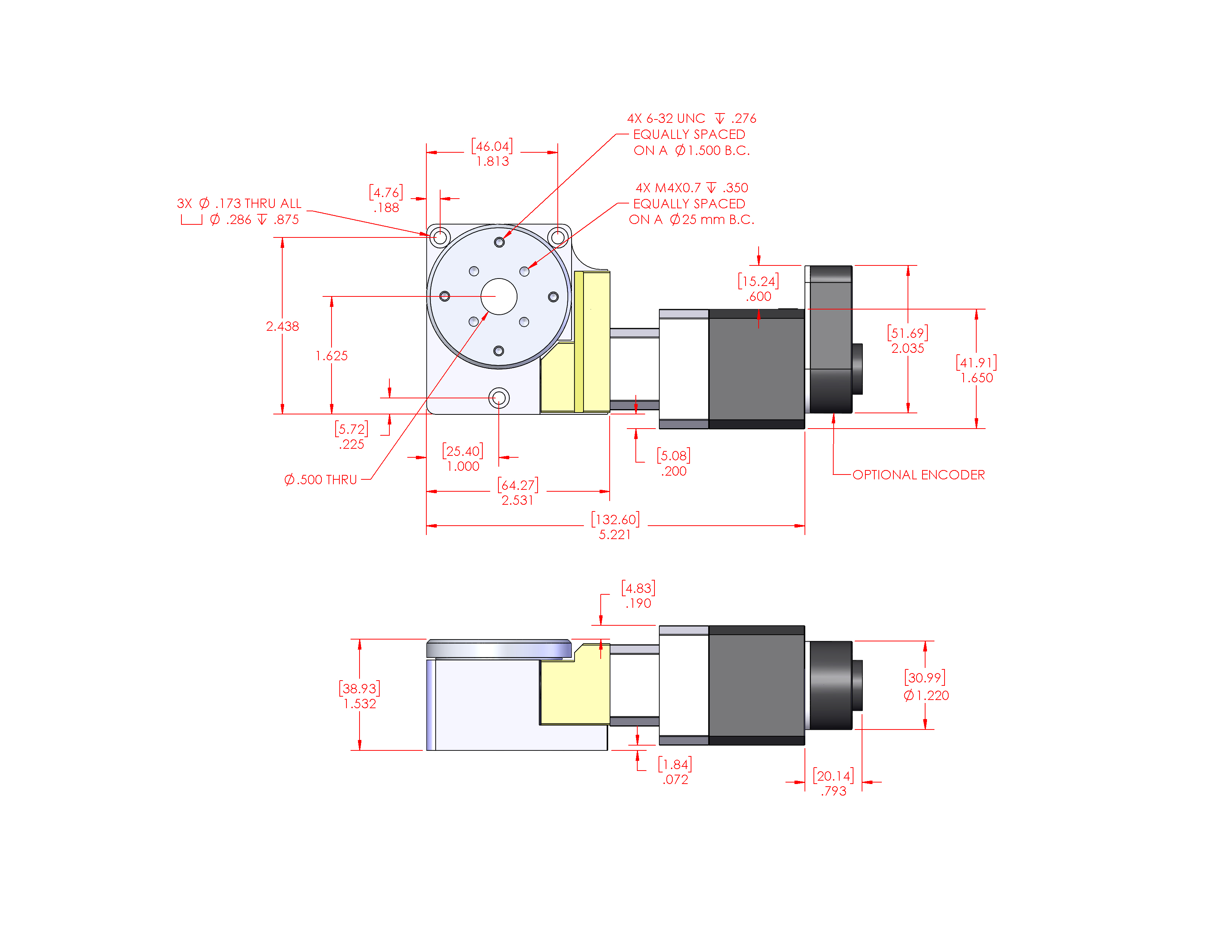